About this page!
TRS-80’s that have sat around for 40 years are very likely to need some tender loving care before they are back in full form.
This page is devoted to repairs and is broken into 3 parts.
The first part is a general troubleshooting guide written by Ken B, who was a Brookner. If you see “KB” as the author of technical bulletings, that is him. This is a good place to start.
The second part covers a blown Model III/4 power supply. This happens so often that it is almost guaranteed to happen.
The third part are prior questions asked, and the answers which were given.
I, of course, take no responsibility for your own repairs. The below are just suggestions. If you wish to have someone else do your repairs, please visit the People who can repair page.
General Troubleshooting Starting Points by Ken Brookner
These systems are old, but not necessarily simple devices. If you do some homework prior to pulling out your test equipment you’ll have better luck chasing down bugs. In our technician training courses we taught these systems to the schematic level in our 6 week courses at that time we troubleshot to the component level. Understanding how the systems work made troubleshooting more efficient which translated into happier customers and increased shop revenue.
Here’s my suggested methodology and tips:
-
Learn your machine by reading the Service and Technical Reference manuals, and get familiar with their contents before you start work.
- Model I Technical Reference Manual
- Model III Technical Reference Manual
- Model III Service Manual
- Model 4 Technical Reference Manual
- Model 4 and 4P Technical Reference Manual
- Model 4 Gate Array Service Manual Addendum
- Model 4P Service Manual
Read the Technical Bulletins for your machine. These bulletins detail upgrades and modifications you may run into on your particular machine that may cause it to differ from the descriptions in the Service and Technical Reference Manuals. Not all machines will have the relevant bulletins done, and you should do the ones listed as mandatory at the very least. In fact, “must” is probably a better word than “should” when it comes to the mandatory bulletins. If you find a machine with the original warranty sticker intact, the Technical Bulletins should be one of your first stops prior to putting your hands into the machine.
- Model I Technical Bulletins
- Model III Technical Bulletins
- Model 4 Technical Bulletins
- Model 4P Technical Bulletins
Read Notes and Jumpers. This extensive two volume set lists most of the systems, boards, and peripherals and offers pictorials to ID what you have. It offers the proper jumper information and in some cases various tips. You’ll save yourself a lot of time by verifying that the machine is jumped properly before diving in. Don’t assume they are correct, or that the jumpers are making good contact after all these years. - Begin with a close physical inspection. Look for burns, connectors making poor contact, anything obvious. Rat piss is conductive! So is concrete dust. As a point of maintenance, better to assume that all dust is conductive, and blow it out.
-
Molex connectors oxidize. This wasn’t a problem 40 years ago, but it is a problem now. At the minimum unplug and re-plug these connectors to hopefully scrape some of the crud off. If you have something like Deoxit, that’s even better.
Same with plug in cards, especially with the 8″ systems. Card edges oxidize and can make poor connection. Be sure your card edges are clean and that the sockets are tight and that your cards are fully and solidly inserted.
Some socketed components may have corroded pins that inhibit good contact. Some may be welded in by corrosion. Usually you can spot these devices by looking for rust on the pins, or pins that appear dark with oxidation. Carefully pull these (see the “Static” comments later in these notes), clean the pins and reinsert. In the worst cases you may have to replace the device, or socket, or both. Take your time when prying the devices out of their socket. - We produced extensive diagnostics for our machines and most of these are available on-line along with their accompanying documentation booklets. If your machine boots, you should run these.
- There often are various board revisions. Find any schematics that are specific to the revisions you’re working on. Chip numbers, test point numbers, and basic circuits can change between revisions. Having matching schematics will save you a lot of time and frustration.
- Don’t overlook alignments. For example we aligned the FDC (if applicable) as well as the hard drive controllers every time a system came into the shop. we didn’t do this just for fun. We checked floppy drive alignments, touched up as needed, or replaced any drive not meeting alignment specifications. Alignments drift. If your machine won’t boot or read a drive, check your alignments. Drive alignment is difficult now since alignment diskettes are almost unobtanium. These were written with special machines and some of the tracks are elliptical. You can’t copy an alignment diskette. Ask for help if you have a drive that seems out of alignment and you don’t know what to do.
- Power supplies: Most often these will be switching supplies and must run loaded. Without a proper load the voltages may be way out of spec or become noisy. In the worst case, you may damage the supply by running it without a load. Supplies differ in where the loads need to be and current draw. When in doubt, all of the voltage outputs should be used as normal for your machine. Some supplies will only require 5V, or 12V to be loaded, but you shouldn’t guess. Find the specs for your supply if using a modern one. We required the Astec supplies to be fully loaded during troubleshooting. You can build a load box if you want and one is detailed in the Model II Technical Reference manual.
- Voltages: Check them and make sure they meet spec! And this includes noise. You’ll need a scope to check noise. A noisy supply will keep your machine from working properly.. including booting.
- In the day we discouraged “swap till you drop” troubleshooting. Today it may be the only way to find a problem. Try not to go crazy until you have an idea of what to swap. We are seeing Z-80 family devices failing as they age, for example.
So, by this point, you will have performed a physical inspection including jumpers, and power supply voltages and noise.
- Next, depending on what your failure seems to be, I’d check to see if the Z80 is running. Be aware that the Z80 is very particular about reset timing. Timing caps are failing or falling way out of spec particularly in the Model 3s and 4s. If you have no activity on address/data lines, check reset timing, or if you don’t have a scope, swap the Z80.
- Clocks: Clocks make the computers run. If the clocks aren’t working or are out of spec you’re going to have a dead or flakey machine. Check them if you have the test equipment. Be aware that it is quite difficult to troubleshoot these machines without a scope.
- Scopes: Having a scope is no help unless you know how to use it. If you’re really green spend some time with the manual and bone up. You should understand coupling, what timebase does, and particularly triggering “AUTO” and “NORMA”L, as well as “SLOPE” and “TRIGGER LEVEL” if you don’t know what these are and why they’re important you have some learning to do. You need to read your manual or watch some vids online if you find yourself spinning knobs and pushing buttons trying to get your scope to display something meaningful. Set your probes to X10 and adjust your volts/div accordingly if your scope doesn’t automatically compensate for this.
- Freeze spray: Often the best way to find an intermittent is to freeze sections of the suspect board. You can buy cans of freeze spray, but canned air (like that for blowing dust off camera lenses) is just as good if you invert the can. If your machine starts up and then fails, freeze spray can help you find the problem area and often the specific device. Sometimes, a hairdryer will help to locate thermal problems, too.
- Static: Static discharges will kill these machines. What many people don’t realize about static damage is that it is CUMULATIVE. The first and second static hit may only degrade a device and it may be the third time, as an example, that finally forces the failure. If you don’t know what a static safe troubleshooting environment is do some research. Troubleshooting on a synthetic fiber carpet is not a good thing. Be aware of humidity levels – lower is worse. I suggest you use a static strap and an antistatic mat at a minimum, but this is up to you.
- CRTs: Be careful. Use common sense. The anode of the tube – this is the cap on the side of the tube, incorporates a bleeder resistor to drain potential from the tube at power off. THESE RESISTORS MAY FAIL OPEN (the one in my Model 16 did). If you are working on the video section you should discharge the tube by attaching a clip lead to ground and the other end to a long screwdriver. Gently insert the blade of the screwdriver underneath the anode cap to discharge the tube. You may not hear anything – which is ok. Whenever working on video keep one hand in a pocket – this keeps you from reaching in with both hands and potentially creating a short path across your heart. I use a back pocket. You should remove any rings, too! Avoiding dropping the tube :slight_smile: if it implodes you’ll have a real mess on your hands or worse. On the back of the tube in the center of the pins is the nipple. It’s easy to break. If you break it, you killed your tube.
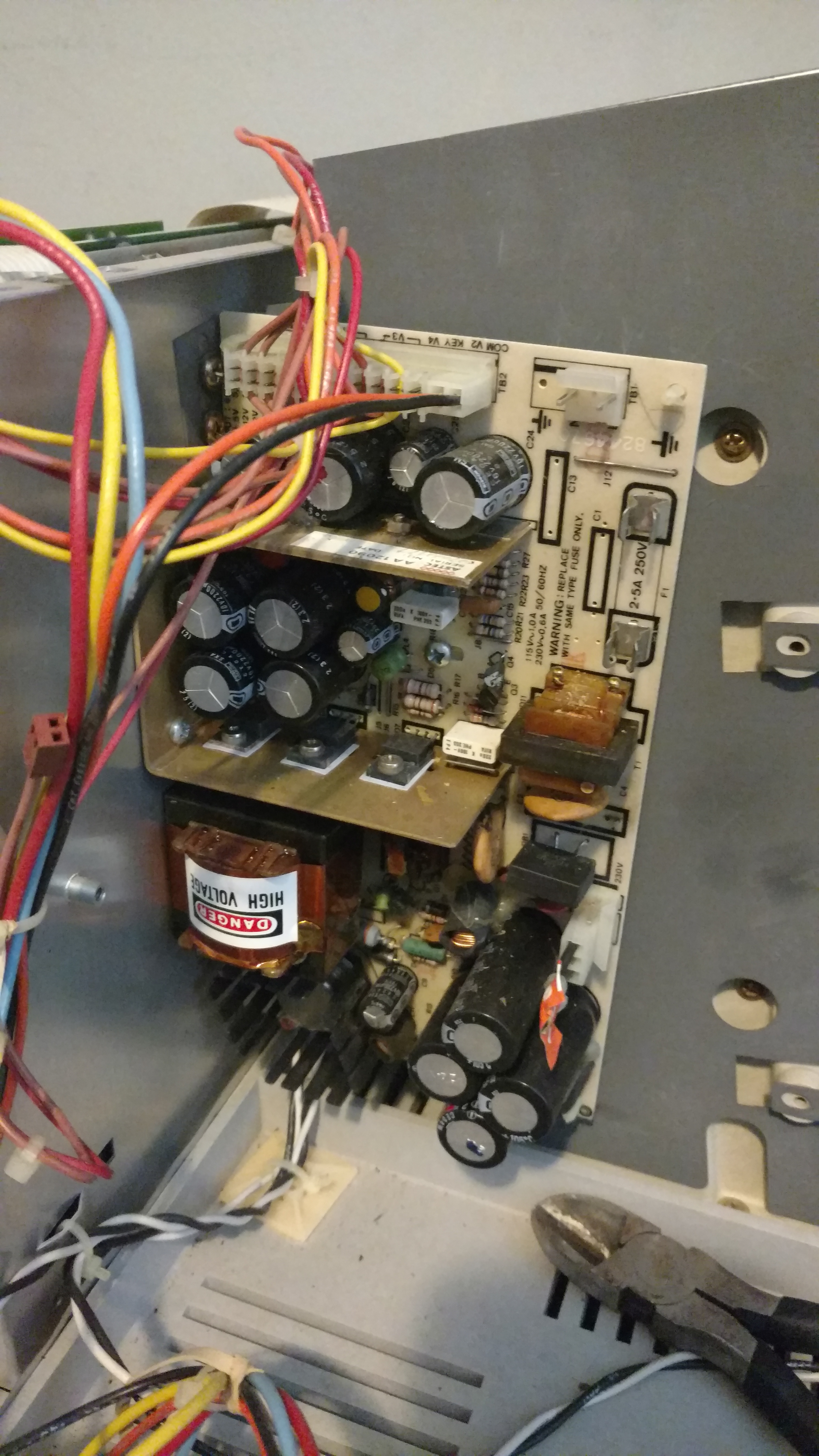
Most Common Issue … Did you Model 3/4 Go Poof!
If you turned on your Model III/4 and smoke came out, it is possible your power supply caps blew. This is very common. To repair it yourself, please see this page.
Per that site, you can possibly find replacements:
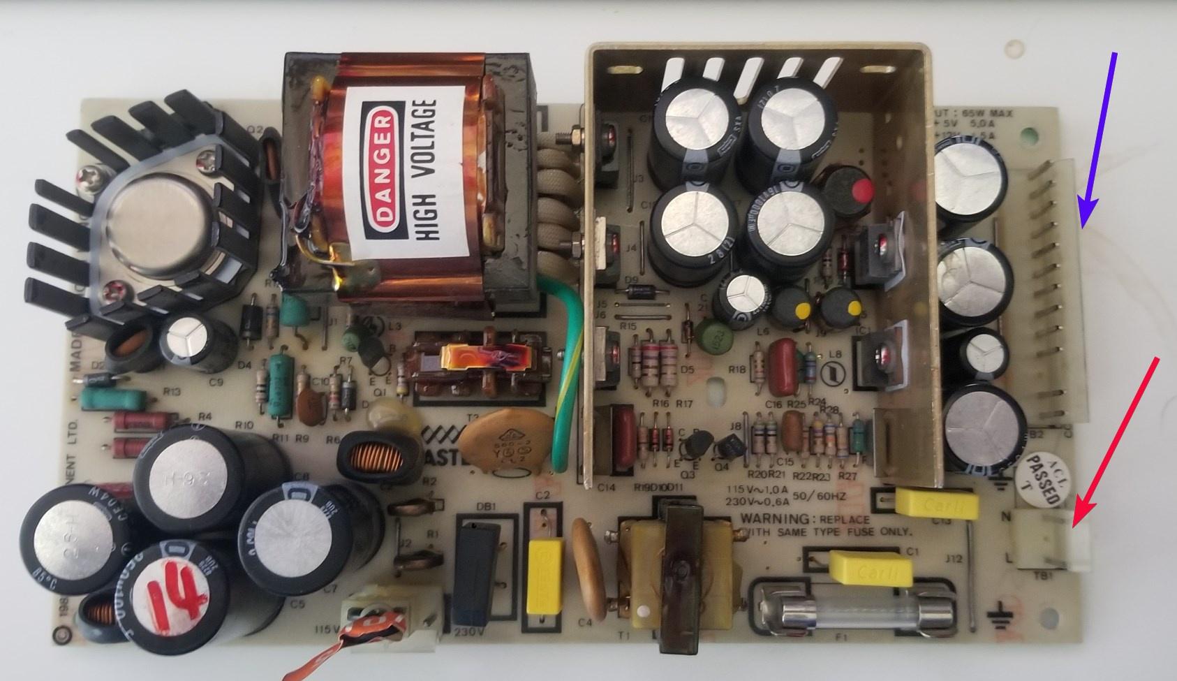
- 0.1uF, 275VAC, X2 cap (Sometimes placed vertically, 3rd vertical item from the word ASTEC):
- 0.01uF, 275VAC, X2 cap (Sometimes placed horizontally between the WARNING and the fuse):
NOTE: I do not make any representations that the information there is correct – do it at your own risk.
If you don’t mind using current components and don’t want to deal with any of that and don’t mind using current components, Jay Newirth has developed a Model III and Model 4 power supply using modern parts. You can purchase the power supply on https://jaynewirth.wixsite.com/newsoft.
TRS-80 Repair
Any hardware which has sat around unused for a few decades may have developed problems in the interim. Solder joints may have detached, belts broken, disk drive heads frozen in position, etc. The following are some questions which had been asked in the past and the answers given. While YMMV, these may be of use. Of course, ANYTHING AND EVERYTHING YOU DO IS AT YOUR OWN RISK, EVEN IF YOU ARE FOLLOWING THE SUGGESTIONS BELOW.
All Models
Model I
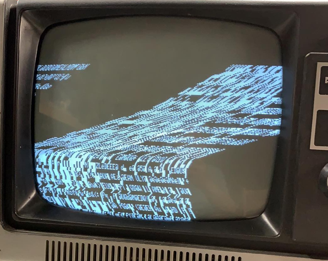
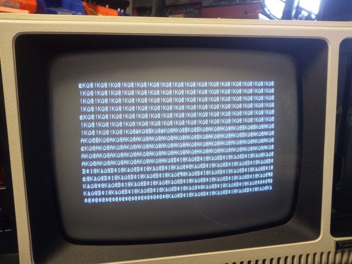
If the screen shows “@9@9” in some areas and garbage characters in others, in a repeating pattern, the defective address line can be found easily. For example, if the pattern is alternately four characters of @9 and four of garbage, then address line A2 is stuck because 2^2=4. If the pattern is a full line of @9 (64 characters) followed by a full line of garbage, then address line A6 is stuck because 2^6=64.

First

Next
and then a second later it looks like “NEXT”. Pressing keys makes no difference and nothing on the screen changes.
Second, try a good Model I on the questionable monitor and see if the picture can be centered on that one and if so, then it is the questionable Model I.
Before proceeding unplug everything and let it sit for a long while.
If its the Monitor, you can take the back off and check that the copper deflection yoke is sitting straight on the neck of the CRT. If it has moved at some point during it’s life it’s going to be sitting on a bit of an angle, that might be you he can’t get a picture to centre on the screen. Alternatively, you can also find instructions to are instructions to build a composite video cable here.
If it’s the Model I, first swing the controls on the back to find the center point. Then open the Model I keyboard and adjust R20 and R21 so the picture is centered on the screen. If THAT doesn’t work, then look at the video sync circuit comprising of Z5, Z6 and Z57 as it’s possible one of those chips (Z5 I would guess) would be going bad.
If both power supplies work, then hook up the Expansion Interface, turn it on, and when turning it off, listen for a second click (not the power switch) that occurs 0.25 seconds after you power down. That is the cassette relay. If you don’t hear a click, the Expansion Interface isn’t powering up. Ian Mavric prepared a video for the click test here.
If you do hear a click, then perhaps you have the wrong cable so, you need to figure out if your Expansion Interface needs a buffered cable with DIN, buffered cable without DIN, or just a regular cable:
If either the Model I keyboard or the Expansion Interface has a DIN plug hanging out of the Expansion Interface port, then they BOTH need that. Click here for a picture.
If the Expansion Interface has no DIN plug hanging out, but has some twisted wires on the SOLDER side of the Expansion Interface, then it needs a buffered cable.
If the Expansion Interface has no DIN plug hanging out, and has no twisted wires on the SOLDER side of the Expansion Interface, then it needs a regular (straight) cable.
Repairing A TRS-80 Model I And Expansion Interface
Model III/4
Underneath:
- 3 short machine screws along the front
- 2 long machine screws about 10cm in and recessed (as the base of the disk drive and base of the CRT)
- 5 self-tappers around the rear, one may be obscured by a warranty label
- 1 black screw in the middle of the back of the computer
BE SUPER CAREFUL WHEN OPENING THE MACHINE – The CRT sticks out, and if you do not angle the case just so, you will damage/break it.
- Open and close the door; lubricate if needed.
- Make sure the head moves back and forth with little resistance; lubricate the rails if needed.
- Check that the drive belt is not too lose or missing; replace if needed.
- Inspect the drive head; clean with rubbing alcohol and cotton swabs if needed.
- Check the felt pad on single sided drives; if missing replace it.
- Clean the solder covered edge connector with a pink pearl eraser.
- If all is well, hook it up and try to format; if it fails check RPM (should be 298).

Click to Enlarge
Click to Enlarge
- Disk drives (2)
- Drive mounting towers (2)
- PSU (1)
- FDC (1)
- Motherboard-FDC white cable (1)
- FDC-Disk drives data cable (1)
- Power distribution cables (3)
- Ground cables (2)
- Assorted RFI shields (3)
- Screws (various sizes)
Model 4:
Model 4P:
Click to Enlarge
One suggestion is to swap Drive :1 and Drive :0 and see if you can boot that way. If so, you drive :0 was bad.
If you still cannot boot, then the problem is likely to be either BOTH drives or the disk controller portion of the motherboard.
The 4P is even easier than the M4 to fix because after the outer case has been removed, the power supply is mounted to a metal panel directly above the CRT – easy access without the possibility of breaking the CRT neck like on a M3 or 4.
If the power supply is Astec then C1, C2 and C13 need to be replaced.
If the power supply is Tandy, then C32 and C33 need to be replaced.
In both cases use yellow Suntan MKT X2 275V caps
It is EXTREMELY rare for any caps on the 4P motherboard to need replacement, so don’t ‘t change anything on the motherboard unless there is an obvious fault.
If it is the disk drives, it is likely that they are out of alignment.
The best bet is to plug in known good disk drives and work backwards.
If you are stuck with a 4P and don’t have good disk drives to test, buying an auto-booting FreHD, and forgoing using disk drives altogether, MIGHT be a solution for you.
Click to Enlarge
Printers:
Click to Enlarge
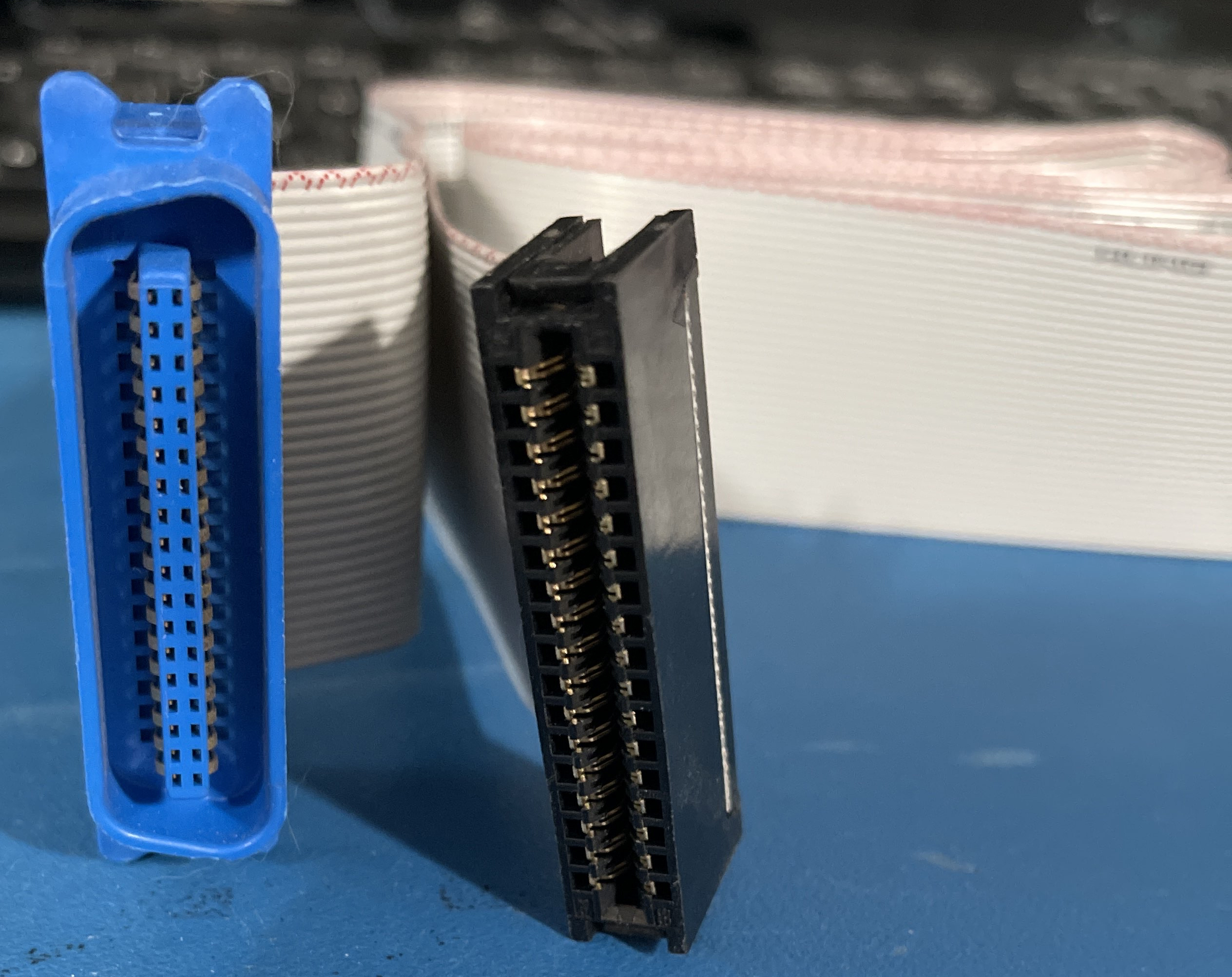
The cable should just be a 34-pin edge card (for the Model III side) and a 36-pin centronics plug for the printer. The centronics plug should have pin 1 labeled (and on the left) so make sure that the pin 1’s match.
Does ANYONE do Model II’s?? I need the legal program as well. How does one hook a 5 1/4 inch disk to a model II? I have a trs dos program on 8 inch disks…..
help?
Trs 80 model 1 boots up to
MEM size
?SN ERROR
If I press the reset button it just keeps saying READY_ but I cannot type anything
Any ideas on the issue?
?SN ERROR is “SYNTAX ERROR”, meaning your Command isn’t understood.
Try typing ?MEM asking the Model 1 to Print the Available memory.
It will respond with the amount it finds.
Larry
I have a TRS-80 Model 1, and I followed the video “How to connect TRS-80 Model 1 to a composite monitor”. I made the wire, and everything is correct. I tried a composite to vga converter to hook it up to a newer monitor, it said something about unknown video signal type, and did not work for this. I also plugged it directly into a flatscreen TV which has composite input, and it gave me a similar error message. I plugged it in to the TV again to get the exact wording for you, but it just says No Signal now. I am doing this because I bought one without a monitor, and on ebay, the monitors are at least a hundred dollars, so I don’t want to have to buy one for my TRS 80 to work. If you could find a solution, it would be greatly apriciated.
I am looking for a replacement cable between the tape recorder and a model 1. Do you know how I might source one?
My sister gave me an old TRS-80 that belonged to her husband’s family. When I power on it stays on for about 5 seconds and the disk drives start spinning and then the pc shuts off. Could this be the power supply even though it initially starts up?
What you describe sounds like a normal start up, it’s not shutting off it just turns off the disk drive after 5 seconds if it doesn’t boot.
Turn the brightness and contrast up to full (if its a Model 3 or 4, there are wheels under the plastic near the keyboard) to make sure the screen is on, and then press and hold the and while you are holding that key down, hit the orange reset button. After you do that, you can let go of the break key.
On a Model 1, 3, or 4 this will show a “MEMORY SIZE” or “CASS” prompt. If that shows up, then you have a system which is behaving as normal when it doesn’t have a disk in the drive.
If not, then the computer likely has a problem
Ira
I recently picked up a Model 4 from ebay and on the power supply, 8709365 Rev C, it appears the Inductor 30uf 5A, at L4, Tandy part # 8419008, leaked and I have not been able to find a replacement. Would anybody know of a current part # that can be ordered?
I realize this is a late response, but L4 being an inductor would be rated at 30uH 5A, not uF (microfarads a measure for capacitors), but again I was not able to find any readily available. maybe consider changing the psu for a more modern one?
On the TRS 80 Model I near R20 and R21 (video pots), there is a 6 pin part that looks like an axial capacitor, but it has 3 pins on each side. The part is marked MEKO, Glendale Calif. 55-1051-10. Does anyone know what this part is? google turns up nothing. I tried to trace the part in the schematic, but it’s throwing me off..
The part you describe is located at board position K1 and is “Relay, Motor Control, 5V” – Controls the cassette. Part 450000.
What a fantastic site.
I bought my TRS-80 Model 1 from the Comp Shop in New Barnet, UK, in 1978.
Saved up for a 4k to 16k upgrade back in the day.
Decided to resurrect it this year. The old TV I used to use has long gone, so I saw one of those TRS-80 ‘5-pin DIN plug to TV Monitor SCART plug’ things on eBay and bought one.
Hooked it up – nothing.
My TRS-80 powers-up, Red light On, but nothing on my Sony TV.
I’m not sure if it’s the TRS-80 or cable or TV or…?
Any advice appreciated!
I have a Model 4P that boots up and runs but when the disk drives run it dims the screen. Is this just a filter capacitor issue or should I check something else also?
All of the diagnostic recommendations from this inquiry have been placed on this page.
I have a Model III, 2 disk system with 32K of RAM and am looking for the correct value that should be returned from ?MEM. What should the value be? My machine gives a value of 31698 when I enter ?MEM. Is this correct?
Thank you
Ken
That is the correct amount of RAM which should show from a PRINT MEM under a Model III with 32K!
where can I buy a 12vcmp3 crt. G2 is shorted on mine. Thanks, Allen
Amber screens are not available. Pete Cetinksi has “RCA 12VCLP4s” in stock.
I have a TRS-80 Model III. When powered up, it will display all @ signs. It also continuously resets itself (not a power supply click, the power supply is silent, it seems that the computer keeps resetting itself every 5 seconds as the monitor never powers off). The drive powers up and looks for a disk before it resets. If I hold the break key down while it resets, I get the Cass? and Memory Size? prompts that stay static on the screen. However, after I press enter to both, the computer goes back to all @ on the screen and continues its reset pattern. Any thoughts on what I should check first? The PS seems OK (there are two of them in this machine), and I have a known working replacement on the way, but this seems like it might be more than a PS failure…
The newer Model 4P power supplies do not have a plug-in connection for the internal Fan. What 12volt positive /Negative wires should I use? Can I tap into the 12Volt lines that go to the Disk Drives?
Hi I have a Model I with 48K ram, a floppy drive and a printer hooked up by switch box. When I go through the power up sequence, the Model I drive keeps running and doesn’t stop, even though all the other components are off. When I turn on the EI and keyboard, the floppy drive still keeps running and doesn’t read any disk in there. The EI’s memory is good. And typically when I turn on the computer, the floppy drive doesn’t run until I turn on the PC, then click the reset button to boot up into DOS.
Any thoughts? Thanks in advance.
Your floppy cable is backwards, check for pin 1
Rick
I have a gate array Model 4… upon power on, it acts like it’s booting (the disk drive spins) if I hold down the break key the disk drive spins and then stops.
There is no video at all.. and no raster if I turn up the knobs. I’ve cleaned all the contacts with deoxyit.
I don’t have any disks, by the way, at all for this machine… and no old PC to make them on either.
Not sure what to try next. I’m not sure if there is a way to check if video is being output by the mb? or some sort of way to hook it up to a modern monitor to see…