Background
The TRS-80 Model I runs at 1.77Mhz, the Model III at 2.03Mhz, and the Model 4 at 4Mhz. These speeds were limited mainly by the Z-80 and the speed of RAM, and were not fast enough to do certain things such as use 8″ drives or use 5 voices on an ORCH-85/90, in addition to being just painfully slow in general. Note: The ORCH-85 software offers built-in options for 2.66Mhz, 3.54Mhz, or 4.0Mhz, and says that failure to use a speed-up for five voices will provide a very limited high frequency response, and such should not be tried below 2.66Mhz. The ORCH-85 will permit you to enter machine language hex code to trigger selected the speed-up.
With this, a number of companies developed hardware solutions to increase the speed of the computers. Almost all solutions were based on the notion that you could take the default system clock of the TRS-80 model and divide it by a different ratio to achieve a faster processor clock. In the case of a Model III, the system clock is 10.1376 Mhz, so a base TRS-80 Model III runs at a ratio of 1/5 (10.1376 MHz / 5 = 2.03Mhz) for its processor clock. By having a programmable divider on the speed-up board, additional processor clock ratios can be calculated. Higher end speed-up boards also included an I/O slowdown circuit (so that your TRS-80 wouldn’t error out on cassette / diskette / keyboard I/O) and a wait state generator (so a sped-up TRS-80 wouldn’t crash by outrunning the ROM or RAM).
While this is not an exhaustive list by any means, this page hopes to touch on many of those options.
A Quick Lesson in Logic
Why do we need a quick lesson in logic? Because the setting of high and low speed always involves enabling and disabling some bits, sent to a certain memory location. Since the memory location may also hold bits for other purposes, you can’t just jam a single value into that location or you risk messing with the other bits which are set.
For example, on a Model III/4, the memory location 16912 and the Port 236 serve a lot of functions. This location/port controls the Cassette Motor on/off, Double Width on/off, Alternate Character Set on/off, I/O Bus enable/disable, and Video Waits enable/disable. If you were just to put a single number in there when trying to turn on and off the speed, you might inadvertently change the character set or turn off the cassette player. Those would be bad.
So what you need to do is understand how to turn on a specific bit, and leave the rest alone. You do this with logical operators such as AND and OR.
When you AND something, you are saying that only bits which are on in BOTH items will be set to on (1), and everything else will be set to off (0). So if you want a bit that’s on to stay on, you use a 1. If you want a bit to stay off, you use a 0.
Instead of that, you might want to say “I don’t care if something is on or off, I just want it on.” To do that you would use the OR command. As long as you have a bit on (1) on one of them, it will be on in the output.
So in cases where you want to force a bit to be on (1), you need to use OR, and in cases where you want to force a bit to off (0), you need to use AND.
Free Option – Model 4 in Model III Mode
The Model 4 normally runs at 4Mhz and a Model III normally runs at 2.03Mhz.
Since a Model 4 is also a Model III, you can get your Model 4 (in Model III mode) to run at the higher speed by sending certain bit patterns port 0ECH (Decimal: 236). The Model III/4 also has a certain RAM Address (16912) which sends data to control port 0ECH, so some cards recommend using POKE, some recommend OUT, and some recommend both.
Because this port partly controls CPU speed, and bit 7 of that port is not used by the Model 4, most speed-up cards use that port to control speed.
Generally, most Model III and most Model 4 software should run at the faster speed. If a Model III program will not run at the faster speed then switch back to the slower speed and try it again.
To get a Model 4 to run at 4Mhz in Model III mode you need to set bit 6 of 16912/236 to ON. Since bit 0100 0000 is 64 in decimal, you want to do an OR 64 against the current value in 16912 to turn that bit on, so A=PEEK(16912) : B = A OR 64 : POKE 16912,B : OUT 236,B would change the speed, while leaving everything else alone. In the case of a fresh powered up non-DOS system, that would be a value of 104.
To turn that bit off, you would need to do an AND against 1011 1111, which is 191 in decimal, so A=PEEK(16912) : B = A AND 191 : POKE 16912,B : OUT 236,B will bring you back to 2Mhz speed.
With these principals, it should be easier to understand the below.
Commercial Solutions
General
There were a decent number of choices to speed up a Model III or Model 4, and most of the instructions say the same thing. To keep this page shorter, the following are the common elements from the below:
First, you needed to make sure you had at least 200 nanosecond memory if not 150 nanosecond.
If your computer crashes after a few seconds of running the following your Z80B may be bad.
1 POKE 16912,40 : PRINT PEEK(16912); : POKE 16912,104 : PRINT PEEK(16912); : GOTO 1
Another commonly recommended system test is:
10 PRINT MEM;:IF MEM < 100 THEN RUN ELSE GOSUB 10
This decreases available memory by 5 bytes each run. If the program runs without issue, your system is probably fine. If it freezes or prints unusual numbers or characters, you have a problem.
Alpha Technology Speedup Board v2.0
Click to Enlarge
The Alpha Technology Speedup Board will run a Model 4 at 5Mhz which they point out is fast enough to run a double density 8 inch drive.
To enter high speed from non-Disk BASIC: POKE 16912, 104 : OUT 236, 104. This sends “1101000” to 16912 and to port 236.
To revert to low speed from non-Disk BASIC: POKE 16912, 40 : OUT 236, 40 . This sends “00101000” to 16912 and to port 236.
The manual also says that for DOSPLUS you would use 120 (Binary: 01111000) to speed up and 56 (Binary: 00111000) to slow down. In reality, that is setting the Model 4 to: Alternate Character Set enabled, I/O bus enabled, Video Waits enabled, and the good old standard Bit 6 on for high speed / Bit 6 off for low speed.
Troubleshooting: If the computer will not work in high-speed mode, you should check to make sure that U3 on the board, the header pins, the Z80B, and the board itself are all properly seated.
The manual can be downloaded here. Thank you to Patrick Bureau for providing the manual.
Anitek Model 4, 4D, and 4P Speed-Up Board
The Anitek Speed-Up Board will run at 5Mhz on a non-gate array Model 4 and 4P and will run at 6Mhz on a gate-array Model 4, 4D, and 4P. This board came with a Z80B, a PAL Chip, and either a 74HCT245 (or 74SC245) chip or a 9-pin resistor pack, depending on whether you ordered the gate-array or non-gate-array version.
To change the speed if you use TRSDOS 6, LS-DOS 6.3, LOOS 5.1.4, or LDOS 5.3, they recommend using SYSTEM (SLOW) or SYSTEM (FAST) from DOS, as applicable.
For any other setup, they recommend using the same old standard of 10 A=PEEK(16912) : B = A OR 64:POKE 16912,B : OUT236,B for fast, and A = PEEK(16912):B = A AND 191 :POKE 16912,B : OUT 236,B for slow.
They also recommend the following patch be made to TRSDOS v1.3 to get it to run reliably in fast mode:
PATCH *0 (ADD=4400,FIND=F5F1F5F1F5F1F5F1,CHG=E3E3E3E3E3E3E3E3)
Troubleshooting:
- If your computer works at slow speed but not at fast speed, you may have slow RAM chips. Check to make sure that they are 150 nanosecond speed or faster. If your compute,r still works at slow speed but not at fast speed, check to see that the speed-up PAL chip is properly seated in its socket.
- If your computer does not work in either mode, check to see that the Z80B chip is properly seated in its socket. If you still cannot get your computer to work, remove the speed-up PAL chip and reinsert the old PAL chip in its socket on the CPU board. Power up the computer and run another test. If it works now, the speed-up PAL is bad. If the computer still does not work, replace the ZB0B with your original ZB0A. If it works then, the Z80B is bad. Return it for a replacement. If it still does not work, you have probably jarred something loose so recheck all connections.
The manual can be downloaded here.
Holmes Engineering Sprinter
Holmes Engineering made speed up board for all the TRS-80 models.
Sprinter I
The Sprinter 1L (which was very similar to the Archbold Electronics Speed-Up Board) was made for the Model I and could go to 5Mhz. Because of this, they had a lot more variables to deal with and installation instructions were on the more difficult side. You were not supposed to use the board if you didn’t have the DIN plug expansion interface cable if you had an earlier Expansion Interface, and instructions varied based on whether you had a revision D, E, or G logic board or had the ROM board attached with foam pads. In all cases, you had to make trace cuts in both the Model I unit and the expansion interface – and in some cases, even to the Sprinter board. With all this, the manual had EXTENSIVE troubleshooting section.
One of the nicer things about this board is that the LED was replaced, so that it would light to green if you were in high speed.
The Model I also posed challenges as disk I/O and keyboard I/O might not work reliably at high speed. If your DOS issued a OUT 254,0 before doing Disk I/O, you were probably safe. If your DOS didn’t do that …. more trace cuts were needed! If you wanted to run an 8″ drive … more cuts.
Instructions were included to use a hardware switch. If you went that route, you could also have your Model I go at 1/2 speed.
The manual can be downloaded here.
Sprinter II
The Sprinter II was also made for the Model I but was SIGNIFICANTLY easier to install. Basically, you would put the Z80A or Z80B into the Sprinter II, bend a few capacitors down (trying not to break them), and plug the Sprinter II into the socket at Z-40. 4 wires then had to be connected to the Model I circuit board: Red to R49, Blue to Pin 6 of Z54, Yellow to Pin 1 of Z41, and Orange to Pin 1 of Z56. You did have to do one trace cut (Pin 5 of Z-69) and they recommended adding two resistors 1K 1/4 watt resistors at R-61 and R-68 to Model I’s with a G revision board. If you had more trouble, they recommended more cuts.
This board offered 16 speeds, all controlled by sending an OUT 254,x command. The x value would set from the available speeds of 1.19 MHz, 1.33 MHz, 1.52 MHz, 1.77 MHz, 2.13 MHz, 2.66 MHz, 3.55 MHz, and 5.32 MHz – Each one with either no wait states or 1 wait state.
Additional modifications were offered to those with more technical skills to disable automatic switching back to normal mode for Cassette and/or Disk I/O.
The logic table for the speeds on the Sprinter II is:
Ratio
Freq.
(Mhz)
States
The manual can be downloaded here.
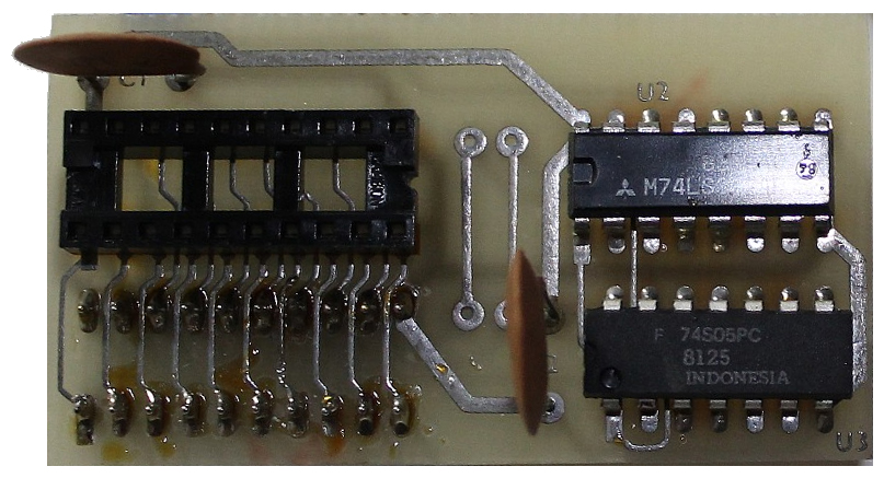
Sprinter III
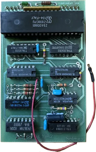
Click to Enlarge
The Sprinter III was made for the Model III (and Xerox 820) computers. It could be programmed to run at 2.02752 Mhz (Ratio of 1/5), 2.5344Mhz (Ratio of 1/4), 3.3792Mhz (Ratio of 1/3), and 5.0Mhz (Ratio of 1/2) in each of two speed modes (0 wait states and 1 wait state). It consisted of five basic sections: a port address decoder, a data latch, a programmable divider, an I/O “slowdown” circuit, and a wait state generator.
Unlike the other speed-up cards, the Sprinter III was basically set to one specific high-speed setting via jumpers on the card itself and one specific low-speed setting via jumpers on the card itself. It comes from the factory set at a ratio of 1/3, giving a processor clock speed of 3.3792 (10.1376 / 3). To pick a different high-speed (or low speed), jumpers needed to be change on the board.
Since the Sprinter III then really only had an ON and an OFF for high-speed, control was much simpler. Sending an odd number to port 95 gave you high-speed (whatever that might be), and sending an even number (or 0) to port 95 gave you low-speed (whatever that might be). The Sprinter III was smart enough to automatically slow down for all tape and disk I/O (resuming high speed once done), although this too could be controlled with hardware jumpers.
Installation instructions were far simpler than on the Model I: Pry out the Z-80, cover the ROM chips so they don’t short out the board, plug the Sprinter III into the Z-80 socket, push the red solderless clip to pin 1 of U-62, and push the white solderless clip to pin 9 of U-60 (to slow down the system for video operations, so it was optional).
Holmes offered special RAM chips with pull-up resistors which they recommended by used in place of the lowest 16K of RAM in the system.
To test whether the system was working, they recommended the following:
10 CLS : PRINT : PRINT @ 0, "RUNNING ........"
20 OUT 95, 0
30 POKE 16919, 0
40 FOR T = 0 TO 20000 : NEXT
50 T1=PEEK(16919)
60 OUT 95,1
70 POKE 16919, 0
80 FOR T = 0 TO 20000 : NEXT
90 T2=PEEK(16919)
100 S = T1/T2
110 PRINT "YOUR SYSTEM IS RUNNING ";S;" TIMES NORMAL SPEED"
120 GOTO 20
The above code set the system to slow, and changed the seconds portion of the internal clock to 0. Then set to high and did it again. It divided the seconds of slow by the seconds of fast and gave you the result.
The manual can be downloaded here.
Seatronics Speed-Up Board
Seatronics made a Model 4 Speed-Up board which utilized a Z80H and could run at 2Mhz, 4Mhz, 5.2Mhz, and 8Mhz. It needed RAM at least as fast as 150 nanoseconds although 120 was a much better idea.
Running at 8Mhz would cause problems with disk I/O. Seatronics recommended changing resistor R20 from 47K Ohm ot 100K Ohm on the Floppy Disk Controller. If you didn’t want to do that, and were running NEWDOS/80 v2.0, you could try the following patch:
SYS0/SYS,02,C3 change 01 40 A3 to 01 50 A3
The speeds were changed by setting bits 6 and 7 on Port ECH according to the below logic table. Since this involves turning on and turning off bits, you would need both an OR (to turn on bits) and an AND (to turn off bits), as discussed above.
Turn off Bit 7 by AND with 01111111 / 127 / 7FH
Turn on Bit 7 by OR with 10000000 / 128 / 80H
Applicable software can be found by searching the Software Archive.
XLR8er
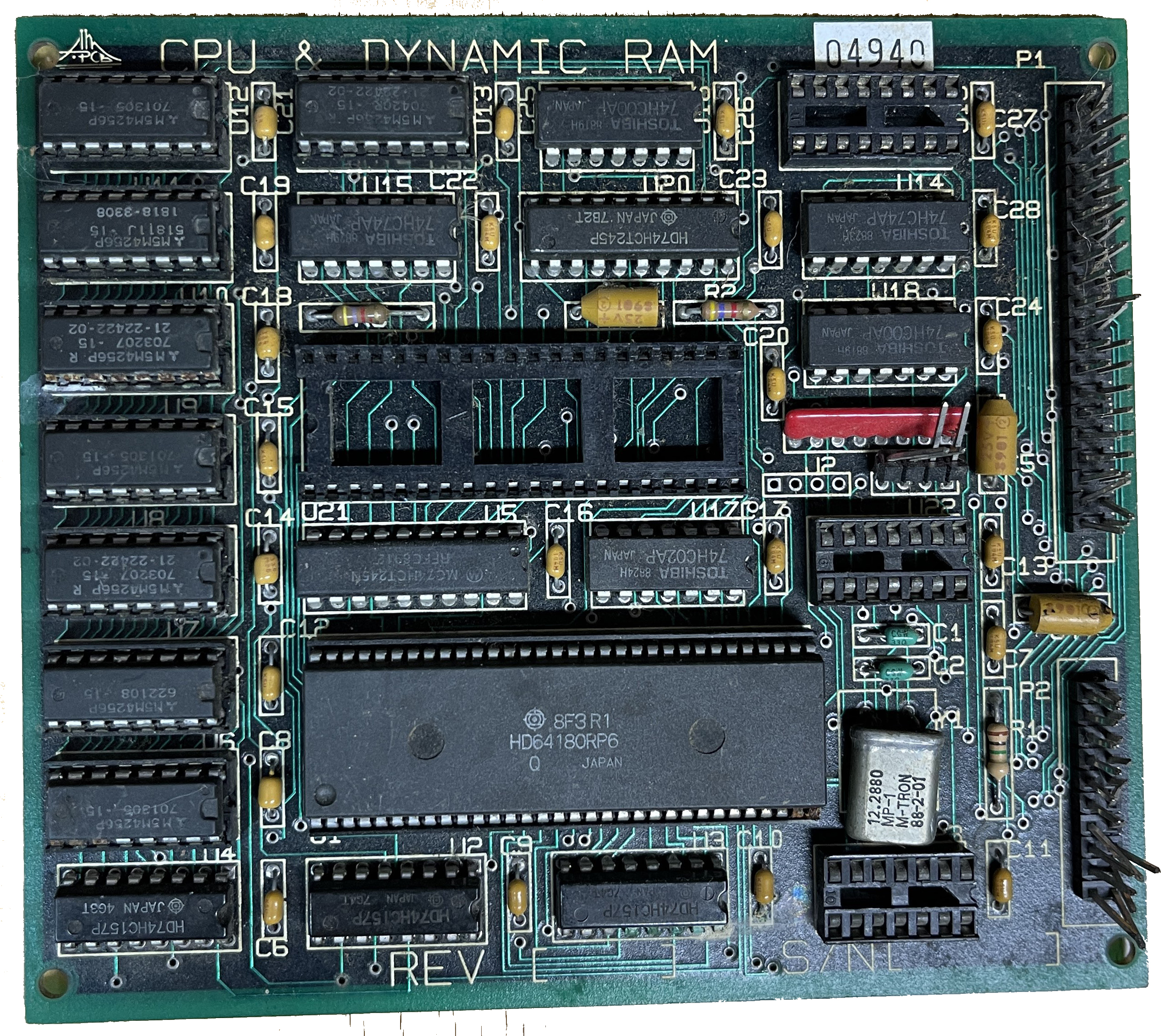
Click to Enlarge
The XLR8er was made by Misosys for the Model 4 and used the Hitachi HD64180 instead of a Z-80 to allow a Model 4 to achieve speeds up to 8Mhz and included 256K of RAM. The main features were:
- HD64l80 microprocessor @ 6.144 MHz (equivalent to a Z80 at 8 MHz)
- 256K of additional high speed RAM
- On chip memory management unit
- Two channel DMA controller (transfers of 1 MB/sec)
- Internal Wait Stale Generator
- Two channel 16-bit programmable reload timer
- Programmable Dynamic RAM refresh addressing and timing
- Interrupt controller with 12 levels of control
- Twelve new CPU instructions including multiply
- OPTIONAL: Two channels of RS-232 communications
- OPTIONAL: Expansion Port
Installation was simple. Plug the XLR8er board into the Z80 socket. Additional changes were needed for rev C and D motherboards and Gate-Array systems required a replacement PAL (Remove 74LS245P from U-77 and replace with 74HCT245P). The extra 256K of RAM could be addressed starting at 40000H.
The Model 4 with an XLR8er would start up with 3 memory wait states, 4 I/O wait states, and a refresh period every 10 clock cycles, leaving it about 23% slower than a regular Model 4. By resetting that to 1 memory wait state and refresh of 80, the Model 4 would run at 70% faster than a Model 4 simply by virtue of the new CPU. This is why there are programs out there to use the “extra 30%”.
To further control the system via software two programs were included: FIXALL and SET180, which were both needed. SET180 controlled the wait states (1-4 wait states possible) and refresh cycle time (10, 20, 40, and 80 clock cycles) and FIXALL was needed to make sure the keyboard would still work (as a slower PAL cannot strobe the keyboard fast enough under the shorter memory read cycle of the H64180). Additional software was included to address the extra RAM.
Installation of that necessary software was handled by the following DOS commands (to attach FIXALL to *WS giving 2 wait states during all keyboard accesses), then SET180 would be run to get rid of wait state:
SET *WS FIXALL/FLT
FILTER *KI *WS
SET180 (MWAIT=0,IOWAIT=1,REFRESH=80)
Software was also included to control Montezuma Micro CP/M v2.3x.
The manual can be downloaded here and applicable software can be found by searching the Software Archive.