Page Menu
- Schematics
- Actual Part Reproductions
- Upgrades
- Printable Parts
- Model I Keyboard Unit
- TRS-80 Model I – Expansion Interface Cover
- TRS-80 Model I – Keyboard Button Placeholder
- TRS-80 Model I – Keyboard Clip
- TRS-80 Model I – Keyboard LED Standoff
- TRS-80 Model I – Keyboard Shield
- TRS-80 Model I – Keyboard Stem ALPS
- TRS-80 Model I – Level II ROM Upgrade PCB Mount
- TRS-80 Model I – Main Enclosure Panel
- TRS-80 Model I – PCB Standoff
- TRS-80 Model I – Screw Post
- TRS-80 Model I – Screw Standoffs Plate
- TRS-80 Model I – Keyboard Spacebar Clip
- TRS-80 Model I – Keyboard Screw Post / Spacers
- Model I Expansion Interface
- TRS-80 Model I – Power Supply Case
- TRS-80 Model III/4 – Keyboard Cover
- TRS-80 Model III/4 – Keyboard Support
- TRS-80 Model III/4 – Key Switch Stem
- TRS-80 Model III/4 – FreHD Bezel
- TRS-80 Model III/4 – FreHD Bezel – 3.5″ Bay or External
- External – Mise and Mise3 Enclosure
- Model I Keyboard Unit
TRS-80 Related Schematics
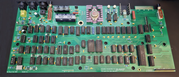
Model I Main Board (Japan)
Click to Enlarge
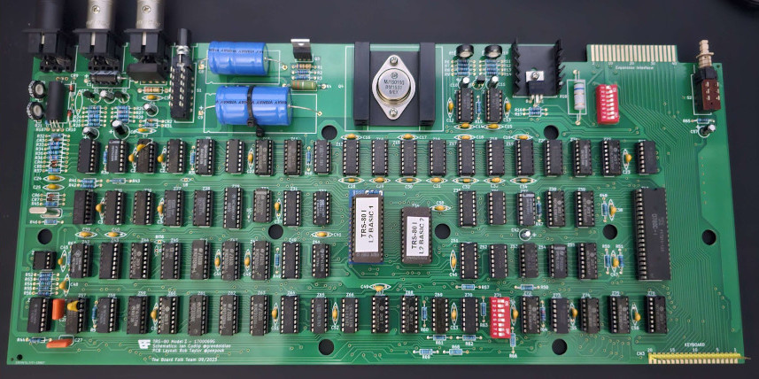
Model I Rev G Motherboard
Click to Enlarge
This is intended as a replica, but additional headers have been provided for the common modification of the 8 bit character set – “BIT6” and “D6” – and “L8” for connection of a character ROM substitute like the Gendon3 module. If original operation with 7-bit characters is required, solder jumper UC should be connected. No additional factory bodge capacitors were added either, for example the ones for the horizontal and vertical sync stabalization. You’ll still need to add those yourself.
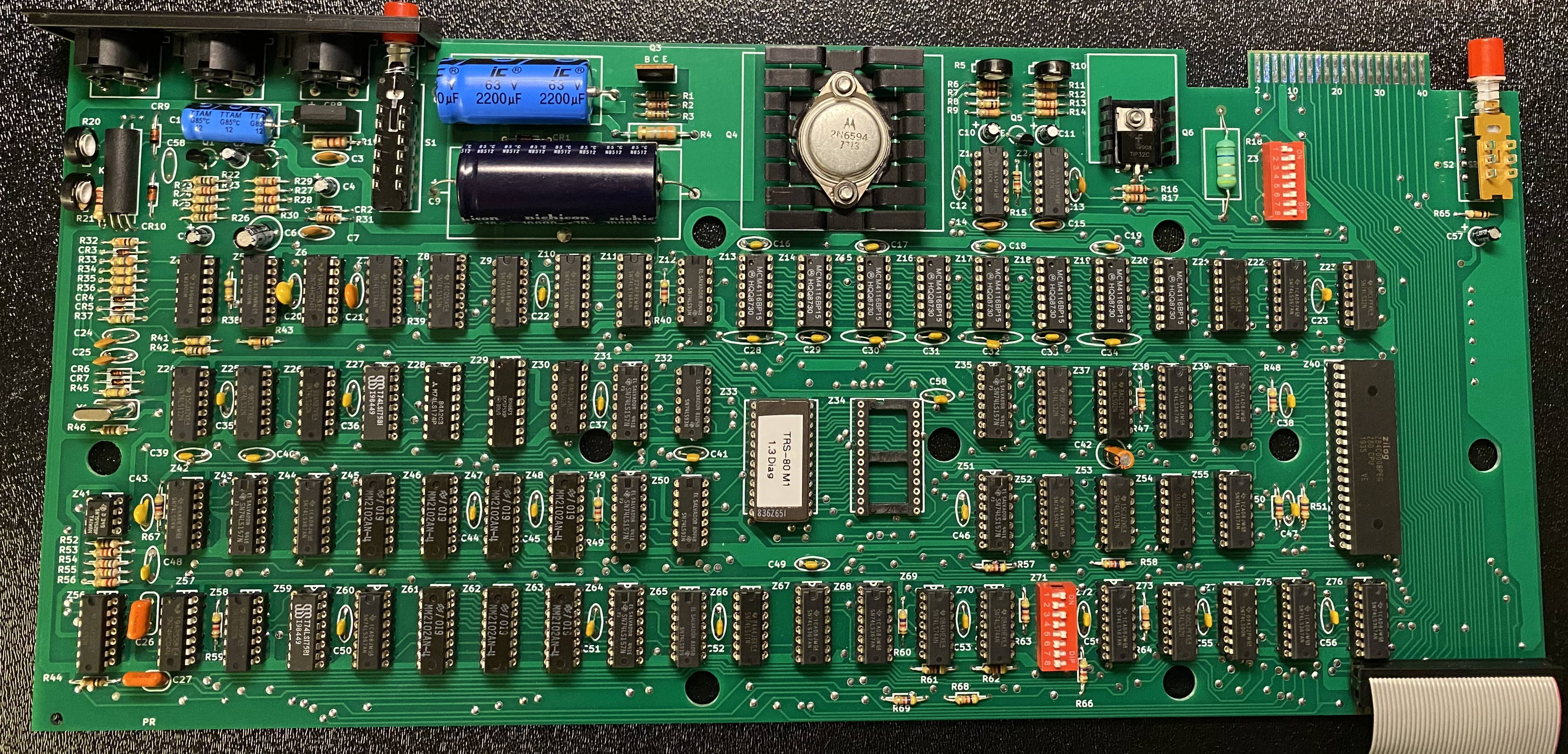
Model I Rev G Motherboard
Click to Enlarge
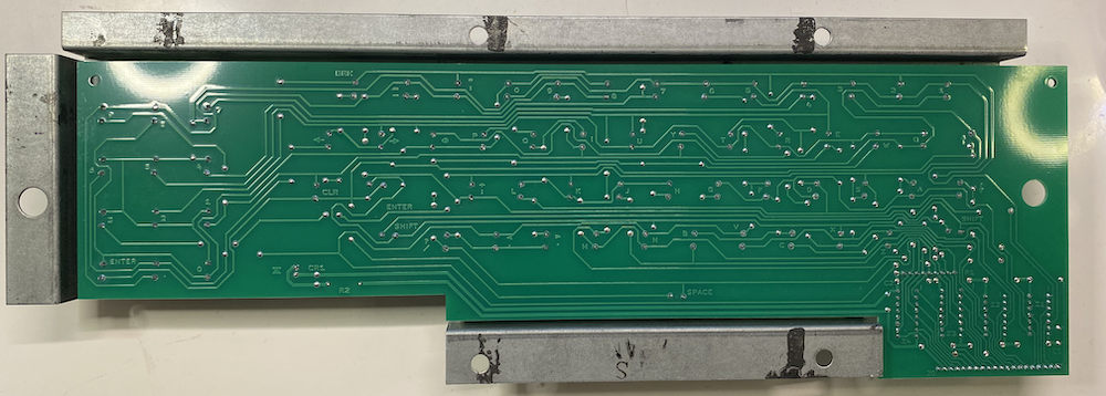
Model I ALPS Keyboard PCB
Click to Enlarge
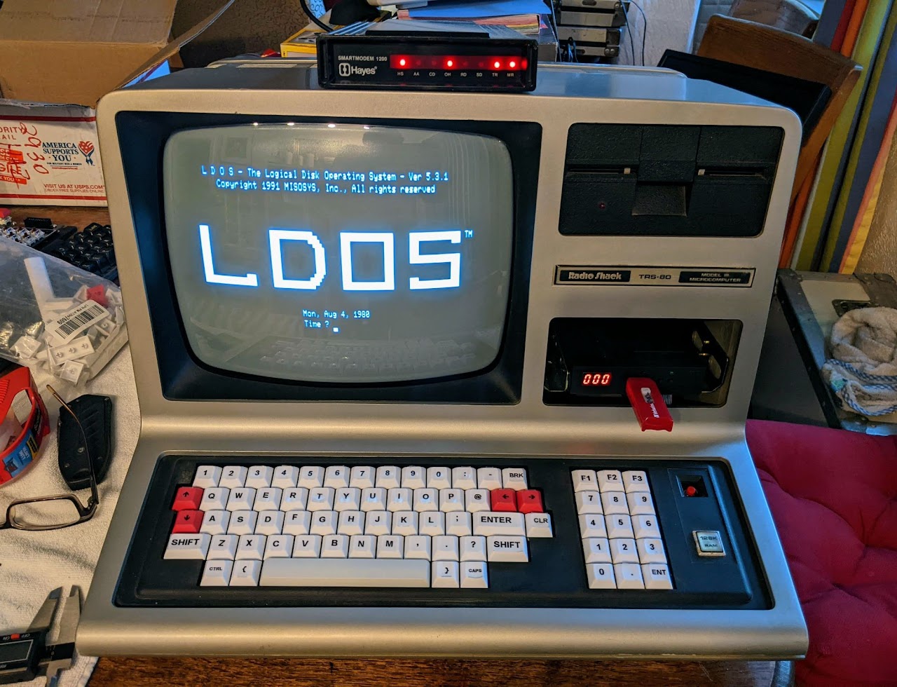
Model 4 Replacement Keyboard
Click to Enlarge
The keyboard is not compatible with the original keyboard plate, but a new compatible plate has been designed courtesy of user alnwlsn on Discord. If mounted above the original plate, the original bezel will not be compatible. When used with a compatible plate, the original bezel will be compatible if the ribbon cable header is installed on the underside of the PCB using the provided footprint and the extra three keys to the right of the numeric keypad are omitted.
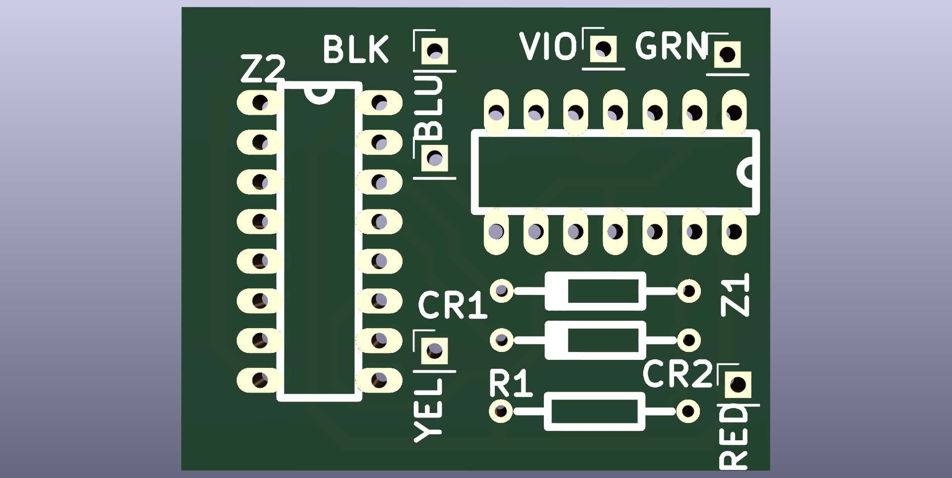
TRS-80 Model I XRX-III Mod
Click to Enlarge
Since this mod is no longer required for the latest ROM version, there’s no need to create it. If you have an older computer, simply update the ROMs, and this mod becomes unnecessary. This repository serves more as a historical record and recreation of the board rather than for implementation.
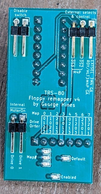
Upgrade – Model III/4 – Floppy Drive Remapper
Click to Enlarge
The main reason for remapping the floppy drives on these computers is to enable booting from drives other than the fixed internal drive 0. This is particualy useful when paired with a modern external floppy disk emulator such as the USB HxC emulator. This avoids the need to take apart the computer, swap cables or replace your internal vintage floppy drives.
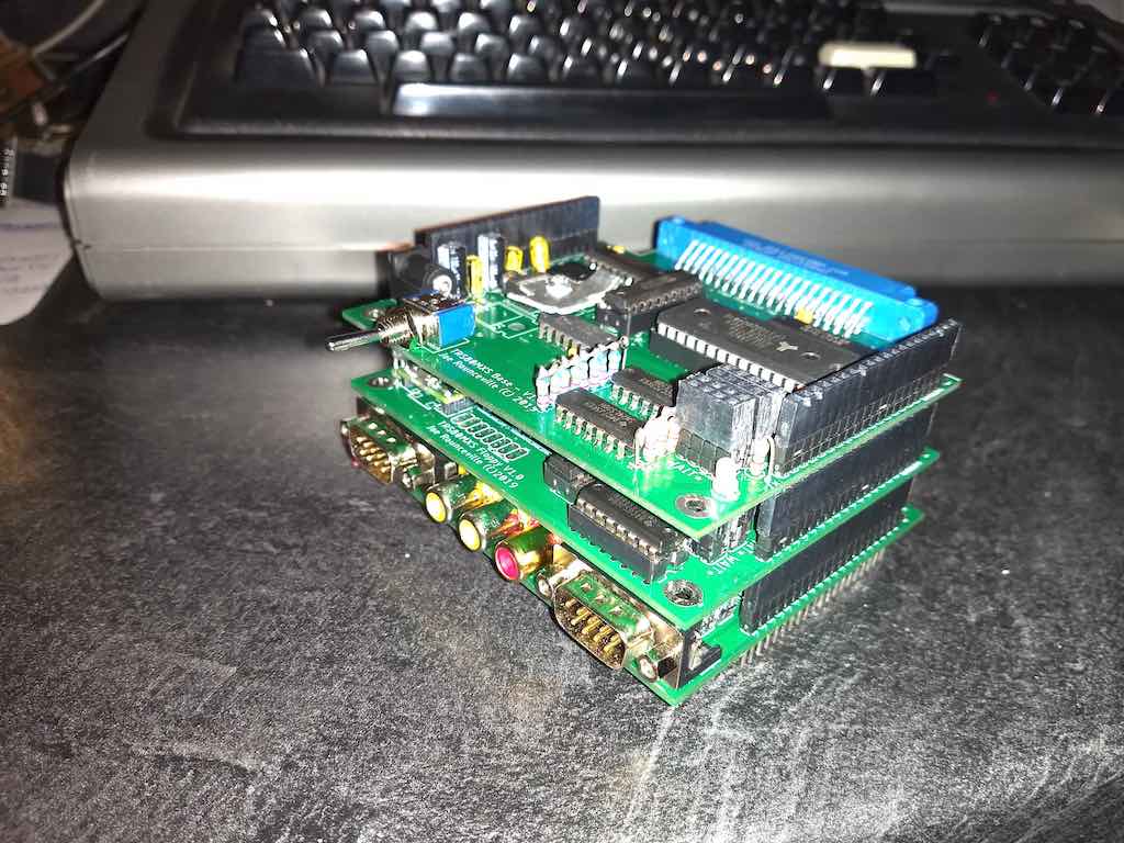
Upgrade – Model I – Modular Expansion System
Click to Enlarge
- Base module – Provides 32K memory expansion, power conditioning, and serves as the base for stacking other modules.
- Floppy drive emulator module – Emulates floppy drives by loading disk images from an SD card.
- TI video/graphics board module – Adds enhanced graphics capabilities using the TI TMS9918 graphics chip, along with sound capabilities using multiple TI SN76489 sound chips (up to 12 voices).
- WiFi module (planned) – Intended to provide wireless connectivity, possibly allowing web browsing on the TRS-80.
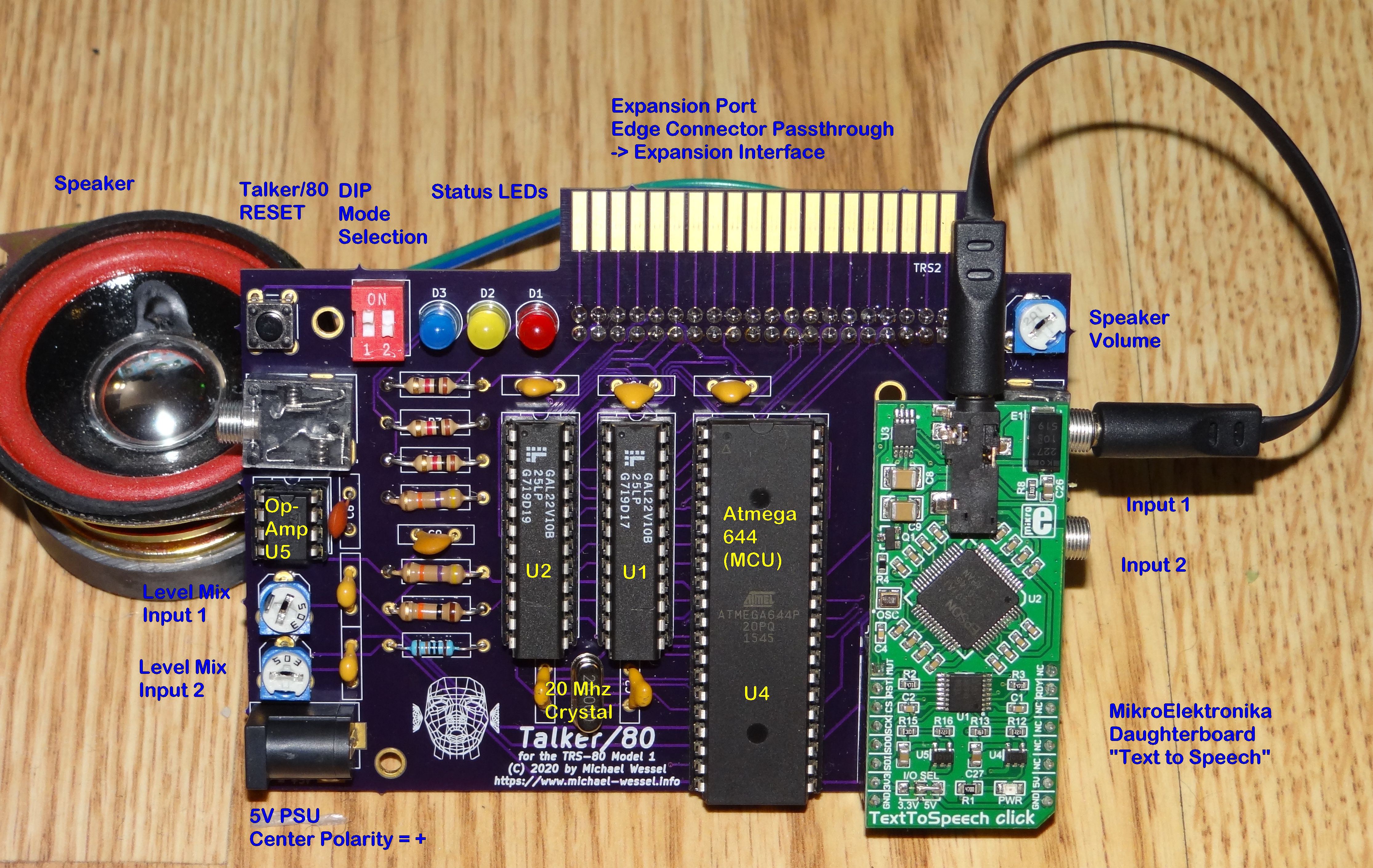
Upgrade – Model I/III/4 – Talker/80
Click to Enlarge
Offers:
- DECtalk-Based Text-to-Speech (TTS) Synthesis.
- TRS Voice Synthesizer Emulation – MODEL 1 VERSION ONLY.
- VS-100 Voice Synthesizer from Alpha Products Emulation.
- Cassette Sound Input Port and Audio Mixer.
- Optional Amplifier and Loudspeaker.
- Expansion Port Pass Through Connector.
- DIP Switch for Initial Mode Selection.
- RESET button: for reinitializing / “rebooting” Talker/80.
- Three LEDs: These LEDs are used for mode indiciation, to signal data being received, to indicate when Talker/80 is speaking, and when a single phoneme is being uttered.
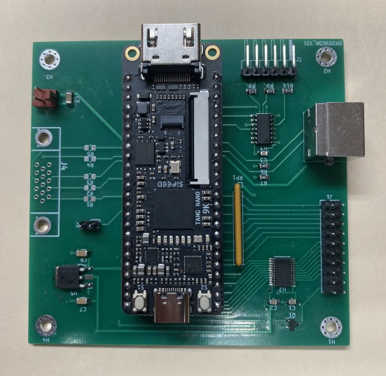
Upgrade – Model III/4 – PS/2 Keyboard and VGA Adapter
Click to Enlarge
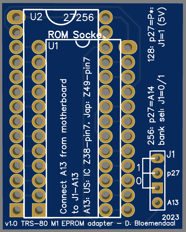
Upgrade – Model I – EPROM module
Click to Enlarge
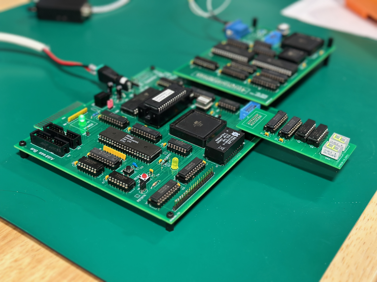
Upgrade – Model I – Super Model I Motherboard
Click to Enlarge
- Z80 CPU DIP 40, 1-16 MHz software adjustable based on installed oscillator.
- 512K FLASH, bankable across all 4 16K regions, write protectable as well.
- 16K of Video memory to support 64×16, 32×16, 80×24 text modes and 512×384 bitmap graphics modes.
- No interference on video access from the CPU. Video access from both CPU and video is full speed.
- 256K of FONT RAM with direct CPU access to allow software fonts (8×16)
- Real-Time-Clock and 192 bytes of NVRAM for setup/boot characteristic.
- Compatible exeternal inteface port for original Tandy/RadioShack Expansion Interface
- Cassette interface
- Work with original keyboard
- Video output: NTSC Composite B&W or VGA 640×480.
- Onboard power regulation from DC input 7-36V. Switching regulator, 94% efficient.
- CPLDS are all ATF1504/1508 family CPLD in PLCC form factor, 5V, 7ns, JTAG flashable.
Upgrade – Model 1/3/4 – Diagnostic ROM
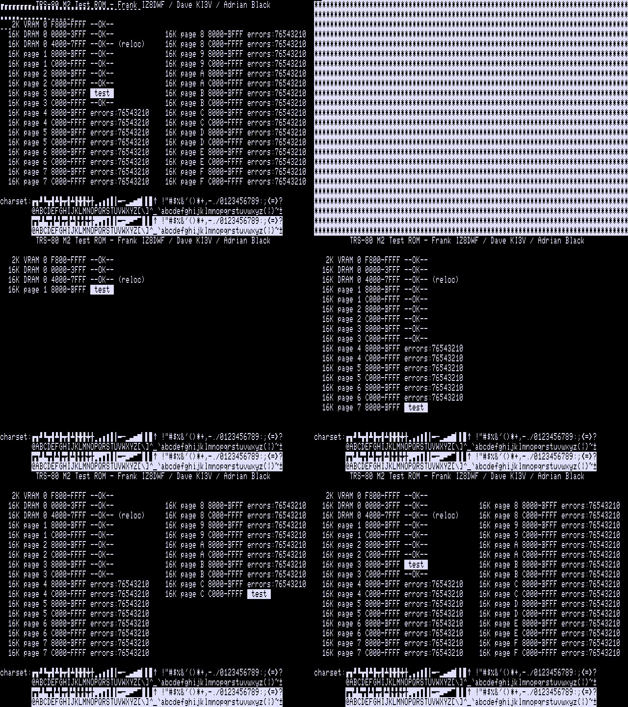
Click to Enlarge
Upgrade – Model III/4 – TRS-NIC WiFi/TCPIP
Click to Enlarge
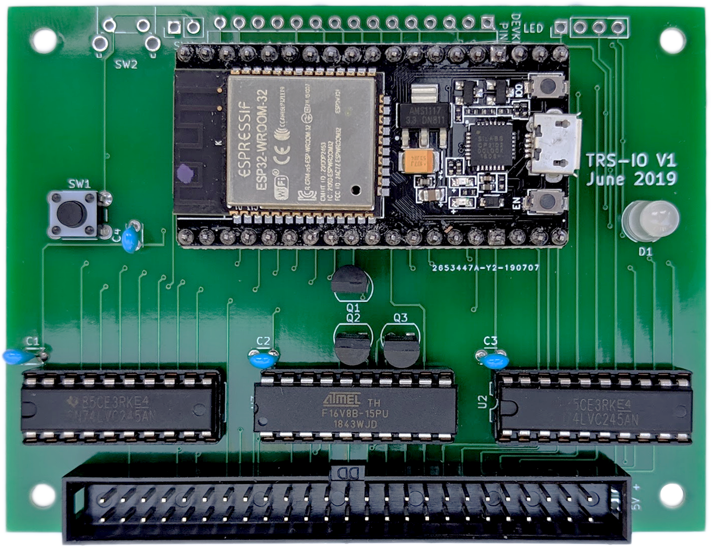
trsnic provides the foundational protocols required to implement existing network interactions on the TRS-80 microcomputer. The first such protocol provided is TCP/IP via an implementation of the Berekely Sockets API. TCP/IP is the dominant low level network protocol in use today. Many of today’s higher level network protocols like HTTP and FTP are implemented on top of TCP/IP. This means many modern networking systems can be built upon the base TCP/IP support provided by trsnic.
Upgrade – Model I/III – TRS-I/O
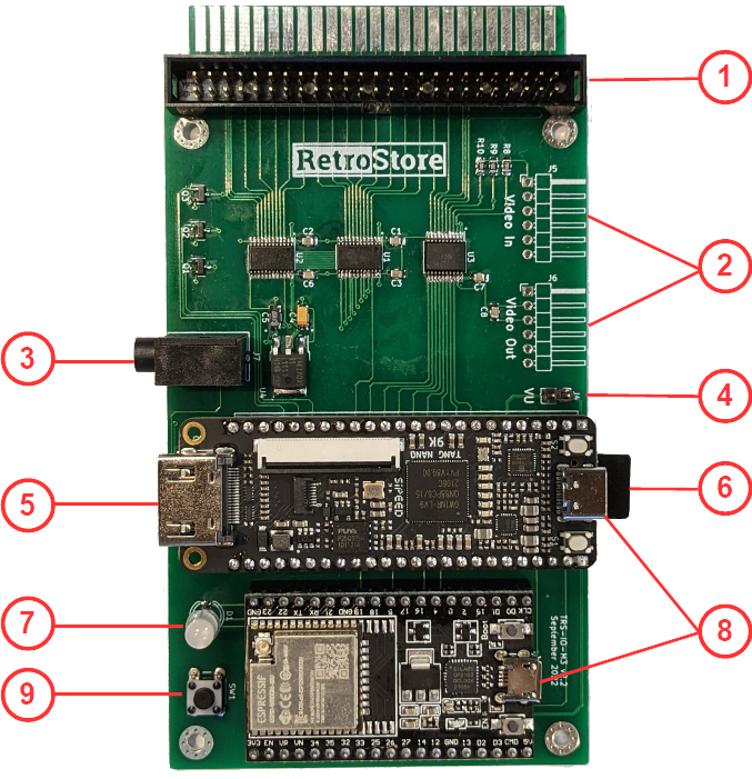
Click to Enlarge
- Access to the RetroStore
- FreHD emulation
- Access to files mounted on a SMB share or located on a micro-SD card
- Access to remote servers via TCP
- Virtual printer support
TRS-80 Related Printable Parts
Note: Treatstock will 3-D print STL images. To order, visit https://www.treatstock.com/c/astra-3d-printing
TRS-80 Model I – Level II ROM Upgrade PCB Mount
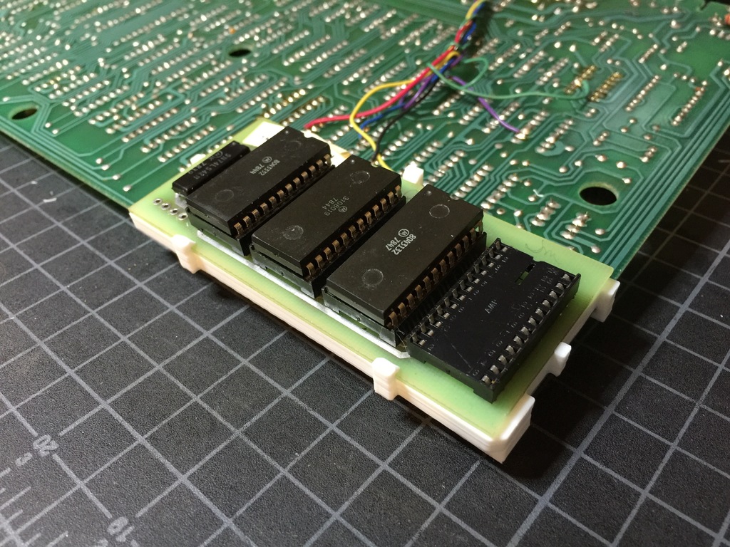
Click to Enlarge
Description:
Mounting bracket for Level II ROM Upgrade PCB, on a Radio Shack TRS-80 Model I computer.
TRS-80 Model I – Screw Standoffs Plate
Click to Enlarge
Description:
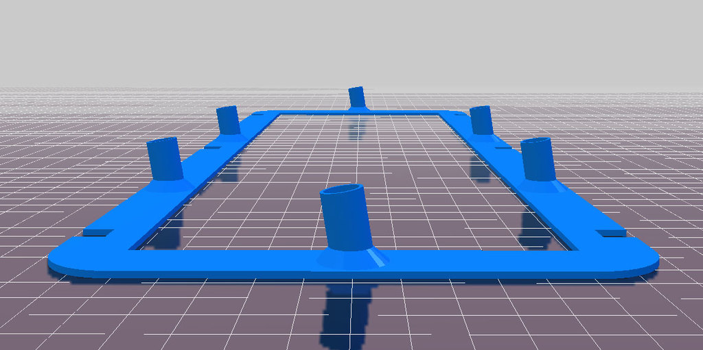
TRS-80 model I computers have screw standoffs that can break or get stripped over time. This screw standoffs plate can be used to replace all screw standoffs completely.
The standoffs plate needs to be printed in two separate pieces due to the length. Unit of measure is millimeters (mm).
To install, remove all original screw standoffs with a rotary tool like a Dremel. Then, use a strong epoxy plastic adhesive to glue the plate down to the surface plane where the original standoffs used to be. Make sure the plate is positioned so that the new screw standoffs align with where the original standoffs used to be.
NOTE: Before permanently gluing this to the case, do a test fit with a hot glue gun.
TRS-80 Model I – Screw Post
Click to Enlarge
Description:
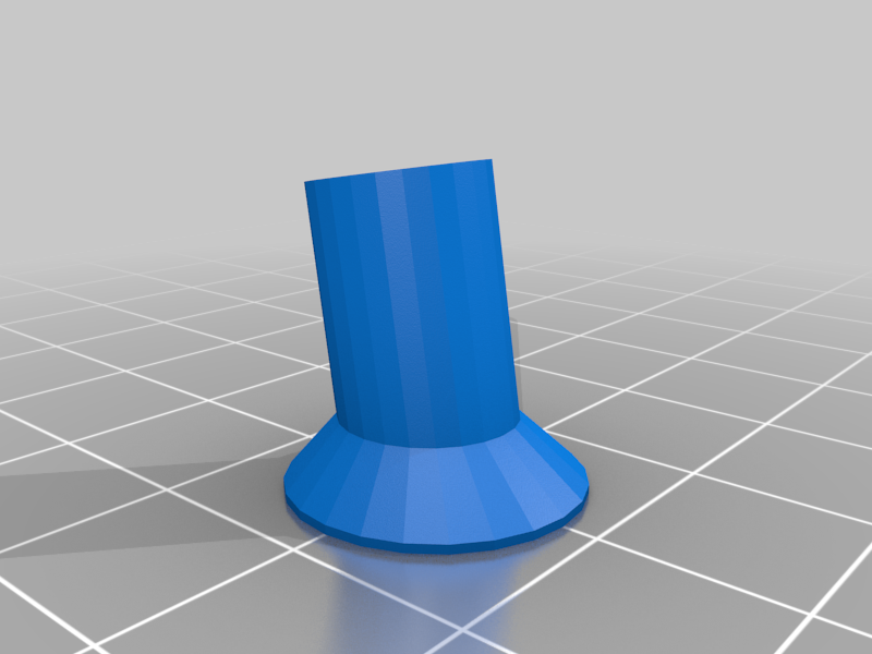
Replacement screw post for Radio Shack TRS-80 Model I computer.
TRS-80 Model I – Keyboard Screw Post / Spacers
Click to Enlarge
Description:
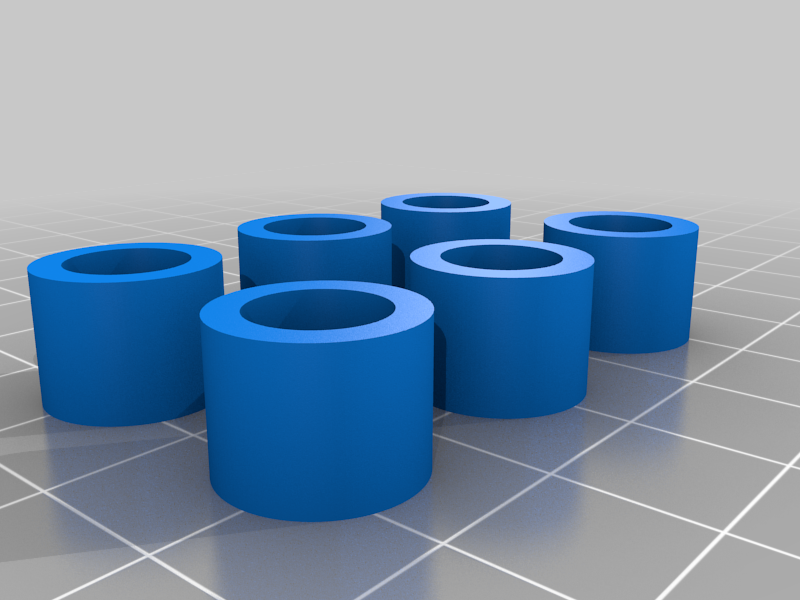
Quick and easy design for the spacers that go in between the keyboard and the mainboard
TRS-80 Model I – Expansion Interface Port Cover
Click to Enlarge
Description:
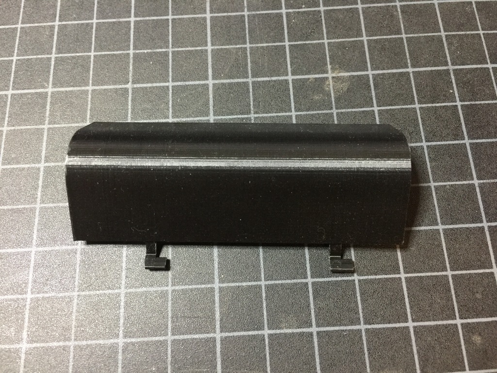
This is a replacement cover for the Expansion Interface port on the Radio Shack TRS-80 Model 1 computer. It’s been modeled by taking precise measurements of an original cover. It fits really well, but you might have to shave off a little bit from one of the sides if it does not fit correctly because the opening on the TRS-80 seems to be a bit angled. Just use a razor blade or even fine sand paper.
TRS-80 Model I – Expansion Interface Expansion Port Covers (Various)
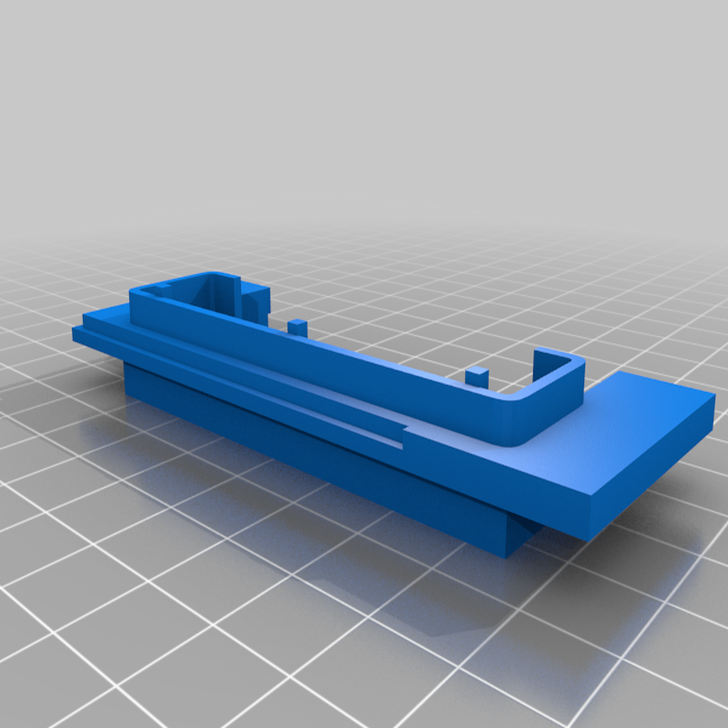
Click to Enlarge
Description:
TRS-80 Model I expansion interface Expansion port covers.
TRS-80 Model I – Power Supply Case
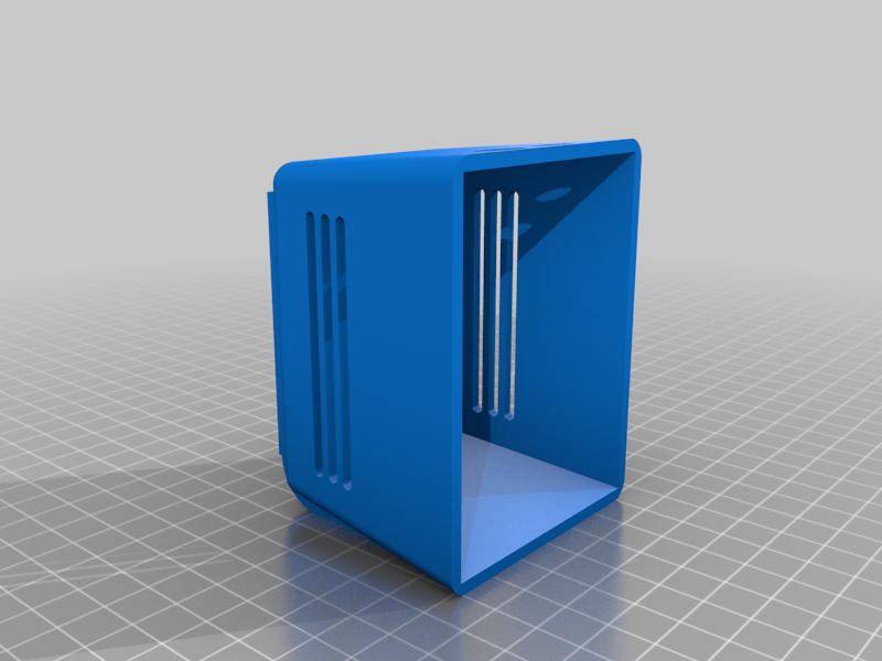
Click to Enlarge
Description:
Replacement for TRS-80 power supply case that came with the model 1. There are several variants of the top part of the case depending on how you want to treat the text on top. There is also a version with vents and text.
TRS-80 Model I – Expansion Interface Power Supply Cover
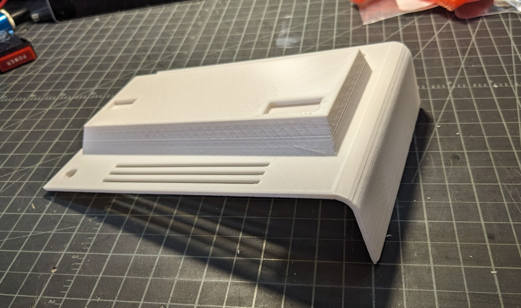
Click to Enlarge
Description:
This is a replacement for the power supply cover for a TRS-80 Model I expansion interface. My unit was missing this cover, so I designed one. I made some revisions to this model after printing mine, so, if you give this a try, please let me know how it worked.
This supports one half of the monitor, so heavy infill is recommended. I would suggest a minimum of 35% — more wouldn’t hurt.
TRS-80 Model I – Expansion Interface PCB Case
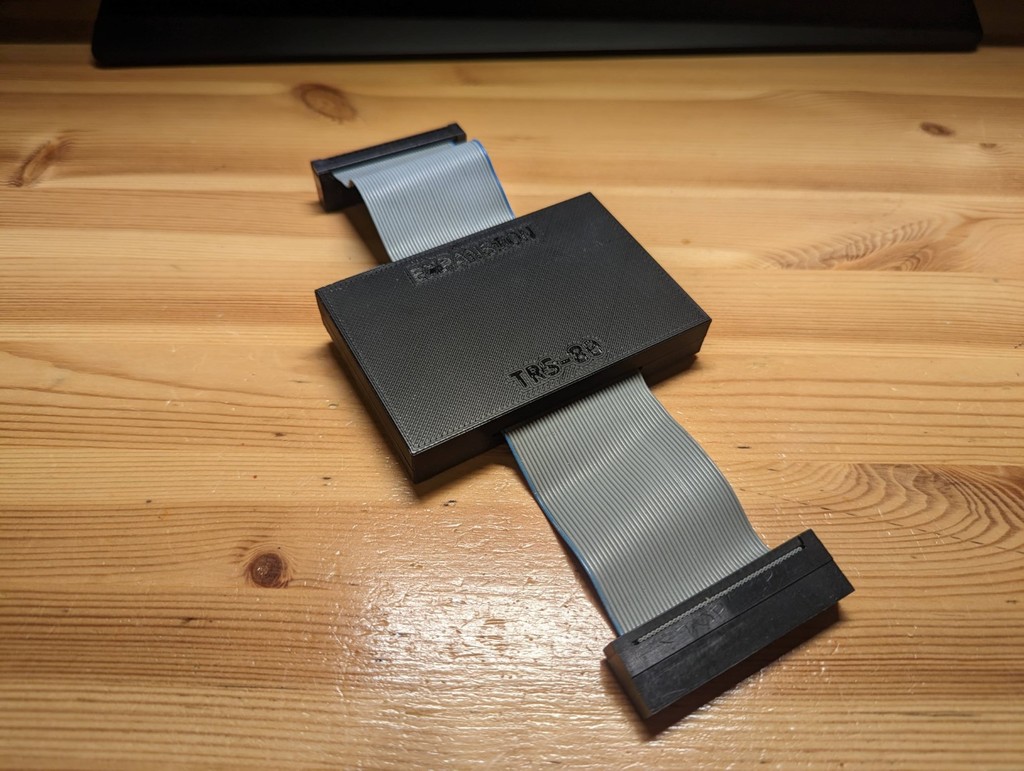
Click to Enlarge
Description:
A simple case for the TRS-80 Expansion Interface PCB. Uses four 8-10mm M3 bolts for similar.
TRS-80 Model I – Keyboard Button Placeholder
Click to Enlarge
Description:
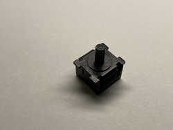
The placeholder is used to guide the Enter key straight down as the ALPS key is located on the other side of the 2x size key. Without it, the key will create too much strain on the Enter-key stem and break it.
TRS-80 Model I – Keyboard Clip
Click to Enlarge
Description:
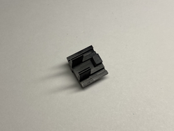
The clip is attached to the keyboard shield and holds the spacebar rod fixed to the keyboard shield. This is the counter part to the Keyboard Spacebar clips.
TRS-80 Model I – Keyboard LED Standoff
Click to Enlarge
Description:
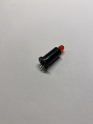
The LED Stand-off gives rigidity to the LED on the keyboard PCB. It also makes sure that the LED easily fits into the casing hole at the keyboard.
TRS-80 Model I – Keyboard Shield
Click to Enlarge
Description:
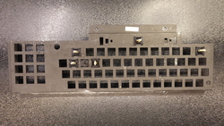
The stem transfers the force from a finger press on the keycap to the spring and simultaneously presses the metal flap inside the button, creating the contact needed for the button press to be recognized. These components easily break and often require replacement.
TRS-80 Model I – Keyboard Spacebar Clip
Click to Enlarge
Description:
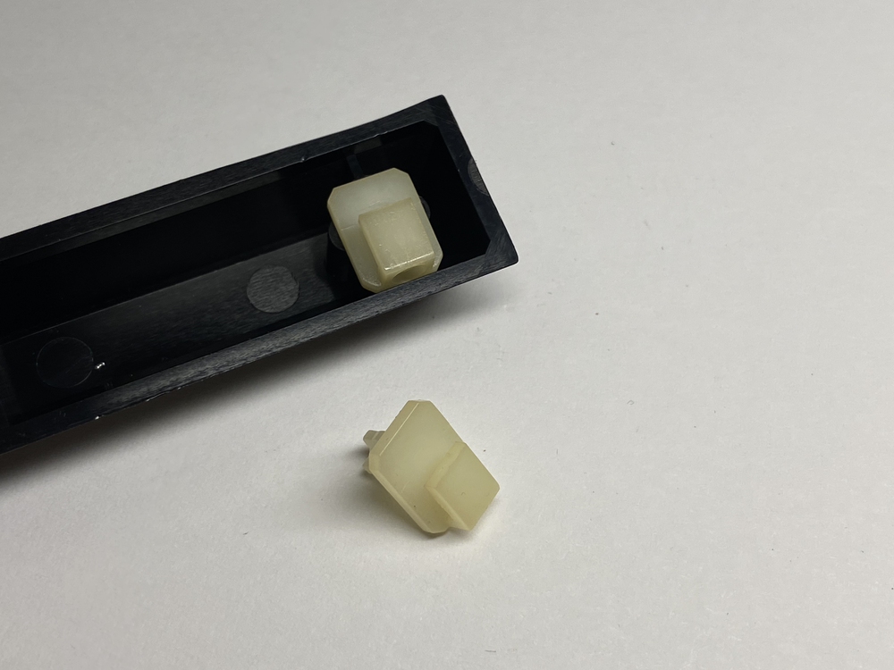
The spacebar clip holds the small metal bar in place to ensure consistent pressure on the button across the spacebar keycap. It also helps to reduce pivoting, thereby decreasing the overall stress on the keycap pin.
TRS-80 Model I – Keyboard Stem ALPS
Click to Enlarge
Description:
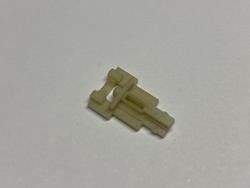
The stem transfers the force from a finger press on the keycap to the spring and simultaneously presses the metal flap inside the button, creating the contact needed for the button press to be recognized. These components easily break and often require replacement.
TRS-80 Model I – Main Enclosure Panel
Click to Enlarge
Description:
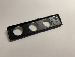
The Main Enclosure Panel is used to cover an opening at the back of the computer, protecting the main PCB. It also provides access holes and labels for power, video, and tape interfaces, as well as a hole for the power button.
TRS-80 Model I – PCB Standoff
Click to Enlarge
Description:
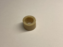
The PCB standoff is being used to separate the keyboard from the mainboard to avoid electronic connectivity. Additionally, since it is made of gummy like material, it buffers each keystroke on the keyboard a bit, reducing the stress on the mainboard.
TRS-80 Model I – Expansion Interface Cover
Click to Enlarge
Description:
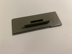
There are three types of covers used: small, medium, and large. I only have the medium, and therefore, only that was digitized.
TRS-80 Model I/III – Mise and Mise3 Enclosure
Click to Enlarge
Description:
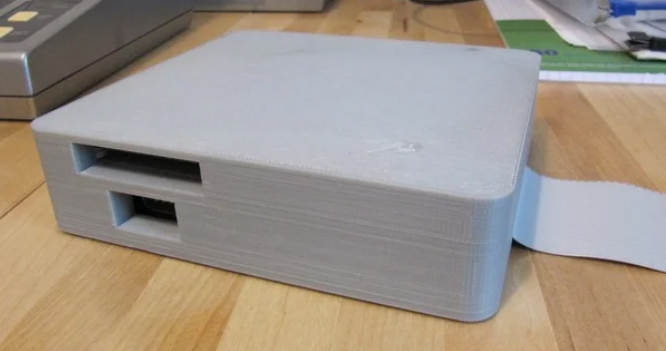
Enclosure for a MISE and MISE3 Add-On Board.
TRS-80 Model III/4 – Key Switch Stem
Click to Enlarge
Description:
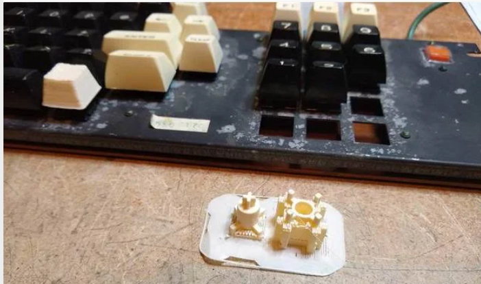
3D-printable replacement for broken key stems. You can desolder the key switch in your system, open them (be careful not to break the clamps which are VERY fragile), and apply conductive paint to the domes.
TRS-80 Model III/4 – Keyboard Support
Click to Enlarge
Description:
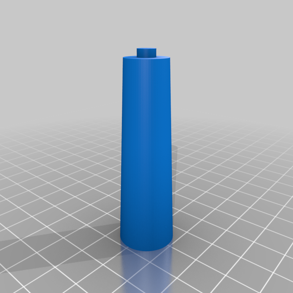
A USB Keyboard support post to be used with a TRS-80 Model 3 or 4.
TRS-80 Model III/4 – Keyboard Cover
Description:
TRS-80 keyboard cover. You need a big build plate for this.
TRS-80 Model III/4 – FreHD Bezel

Click to Enlarge
Description:
Design modified by Jay Newirth of newSOFT fame. Jay created a period-perfect FreHD bezel for TRS-80 Model IIIs and 4s. Using this design, with a couple of extra finishing touches, including the most perfect FreHD badge you’ll ever see, you’ll keep your M3/4 with one foot firmly planted in 1983, and the other in the gigabytes of the 2020s.
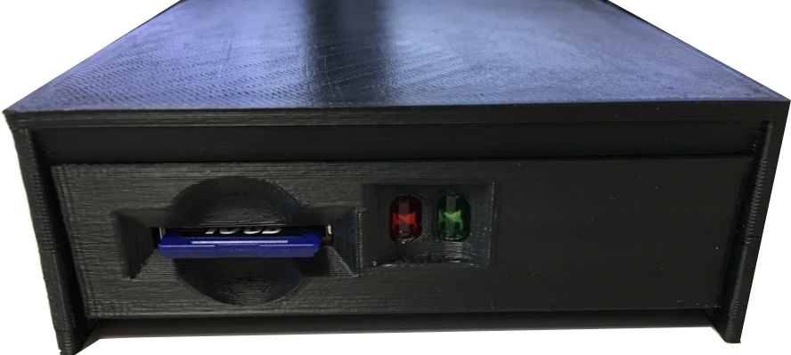
TRS-80 Model III/4 – FreHD Bezel – 3.5″ Bay or External
Click to Enlarge
Description:
This will allow for mounting a FreHD TRS-80 hard drive emulator in a 3 1/2″ drive bay. There are versions for two FreHD board layouts (Rev 3.01 and 3.03) and an LED back plate. For more information see the TRS-80 Model 1-4/4P group on Facebook.
The photos show it mounted in a 3 1/2″ to 5 1/4″ bay adapter.
2 adapters are for 3.01 and 3.03 Rev FreHD have only bottom mounting holes and the other 2 have both bottom and side mounting holes. The ones with the side mounting holes have the _1 suffix.
Newly Added, cover.stl. A snap on cover for the bay adapter to make a full external enclosure.