Model 4:
Note: Keep track of which screw goes where. Many of the screws need to go back into the same places they came from. Follow these instructions at your own risk and make sure the unit has been unplugged for at least an hour before attempting!!!
Steps:
1.
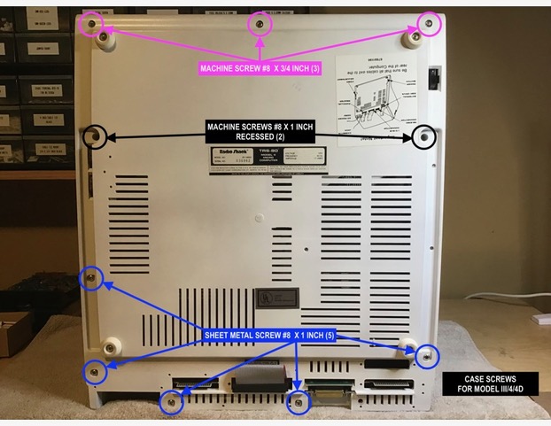
Remove the 10 screws on the bottom, keeping track of what went where.
2.
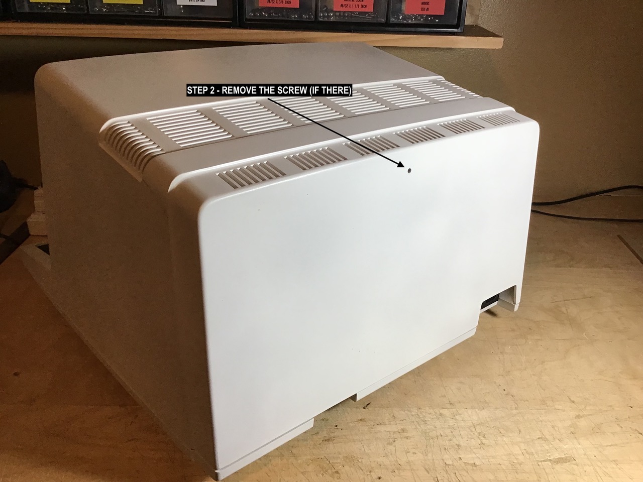
If your Model 4 has a screw on the back top center, remove that. Not every Model 4 has this screw.
3.
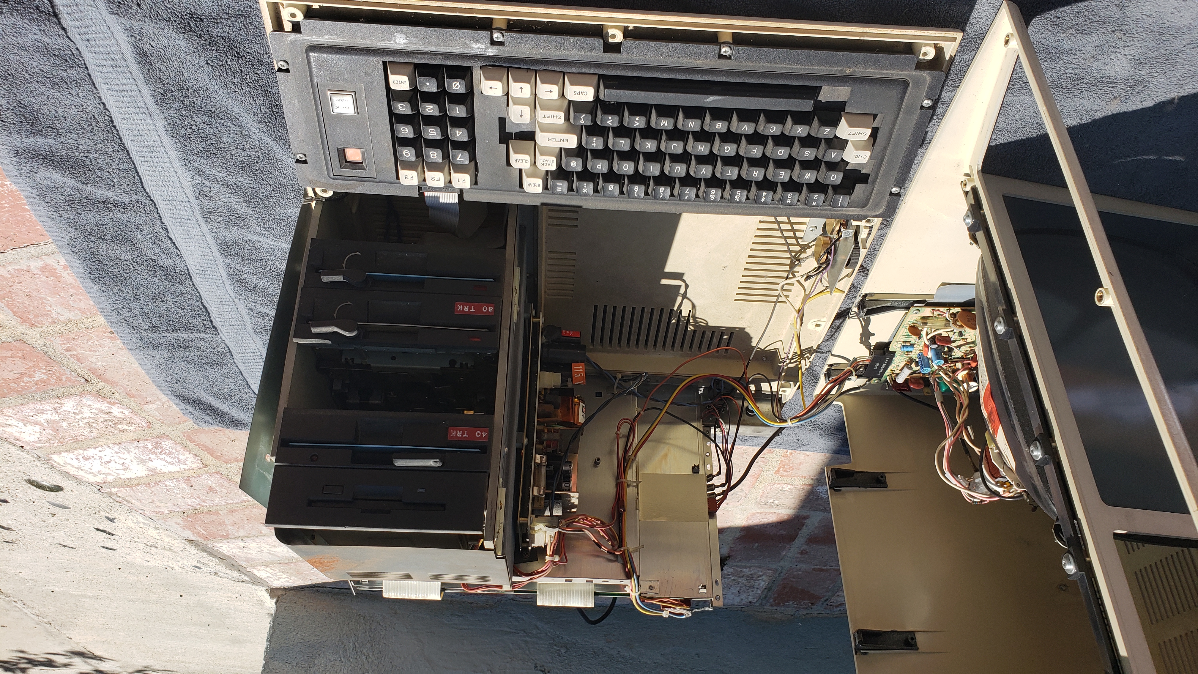
Open the case VERY carefully because the video tube and attachment can EASILY catch and break on the wires or the frame, so GREAT CARE must be taken with the next step. You can try to look through the floppy drive holes or the vents at the top of the model 4 to make sure you have cleared the CRT Tube. With the front of the Model 4 facing you, lift up a little and then pull forward a little. Tilt the cabinet to the left after you have cleared the video tube.
4.
Lay the cabinet/monitor on its left side (disk drive openings up).
5.
(OPTIONAL – If you need to get to the motherboard) – Now you have it open, but you cannot fully access the internal as there is a RF shield present, so remove the RF shield screws and then the RF cover.
That’s it for opening the Model 4. To close it, do the steps in reverse. If you are trying to access / replace / fix your power supply, follow these additional steps:
6.
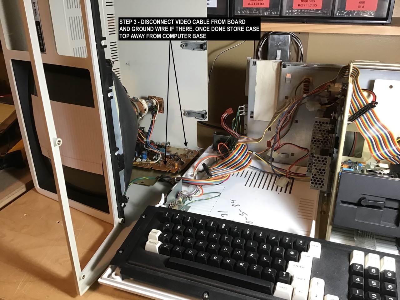
(OPTIONAL – For ease of maneuverability) – Remove the video connector and ground plug (if there), then move the top out of the way.
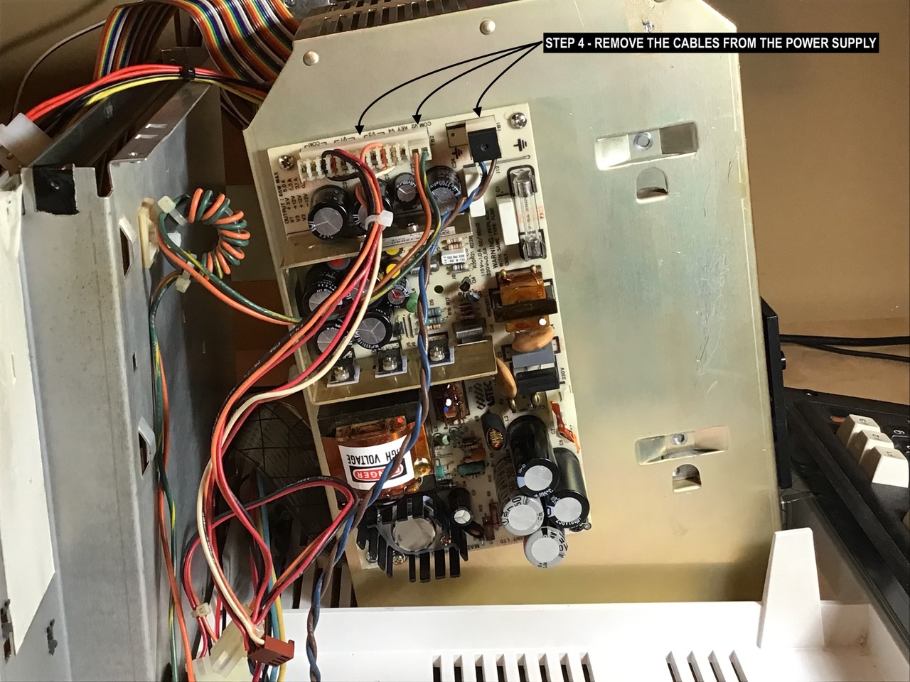
7.
Remove the 3 cables attached to the old power supply.
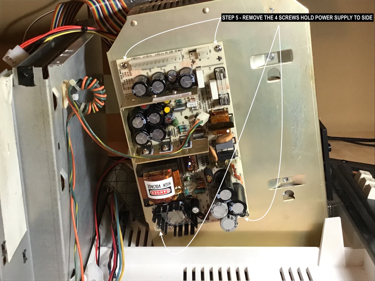
8.
Unscrew the 4 screws holding the powers supply to the case.
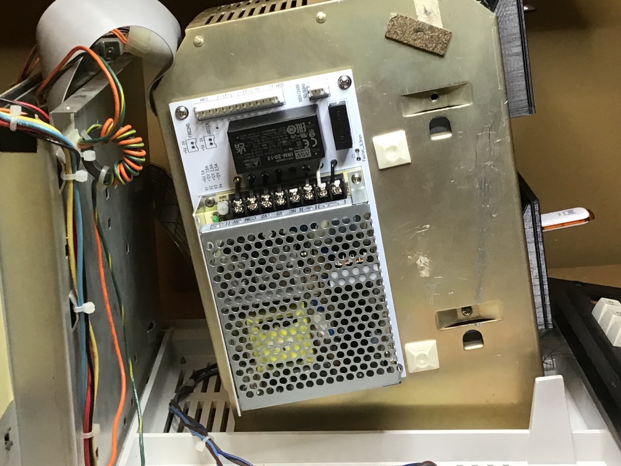
9.
Attach the new power supply with the connectors on the top.
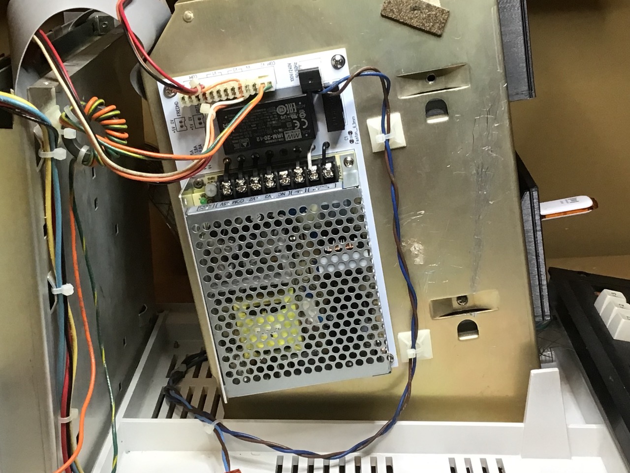
10.
Re-attach the 3 cables – make sure the “lip” edge of each connector faces up. Connector should “snap” into place if cable oriented correctly.
11.
(Only if you did step 6) – Lay the top of the case to the side of the base and re-attach ground wire and video cable. Video cable has a “key” so that it can only go on one way.
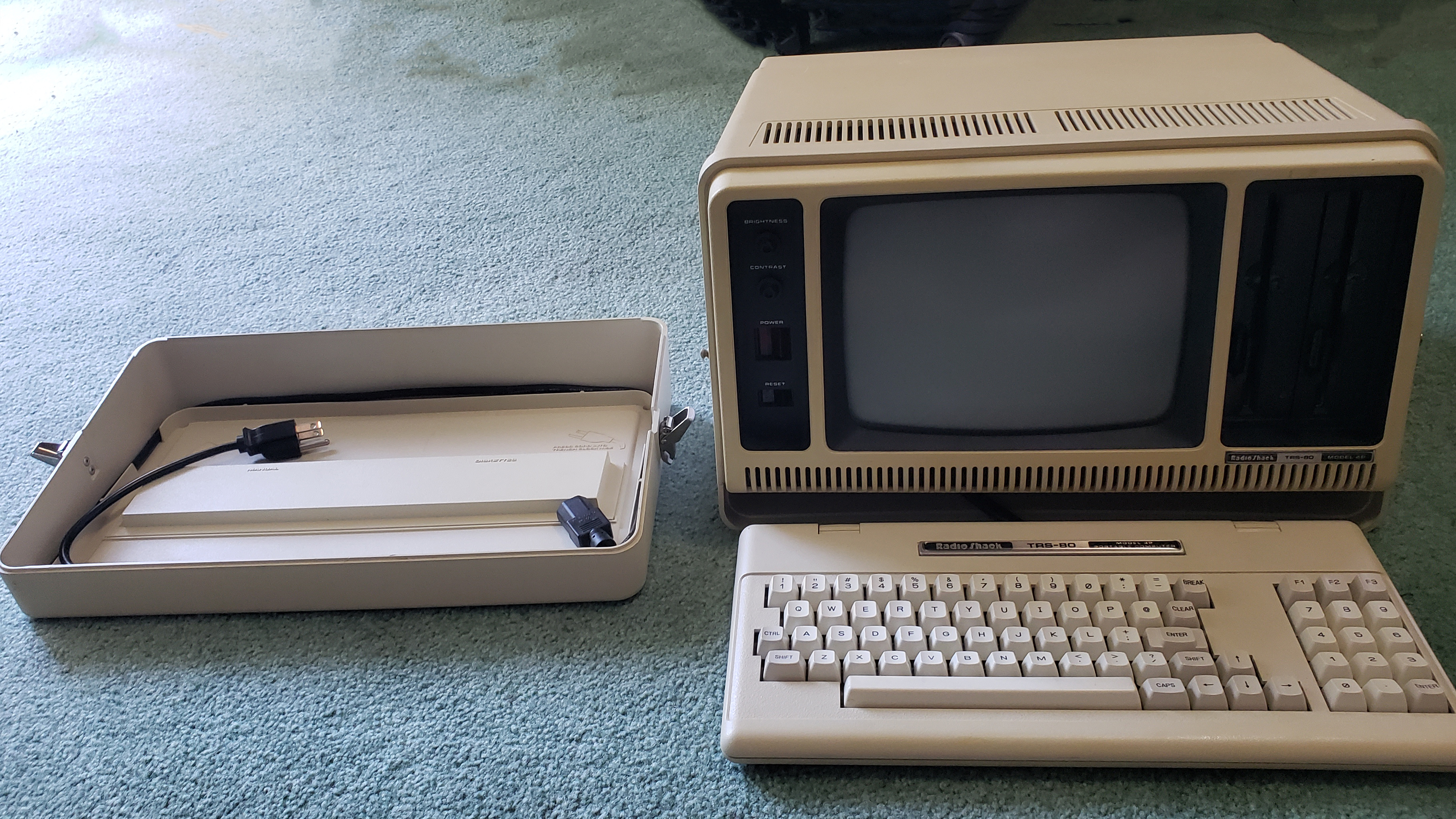
Model 4P:
Note: Keep track of which screw goes where. Many of the screws need to go back into the same places they came from. Follow these instructions at your own risk and make sure the unit has been unplugged for at least an hour before attempting!!!
Steps:
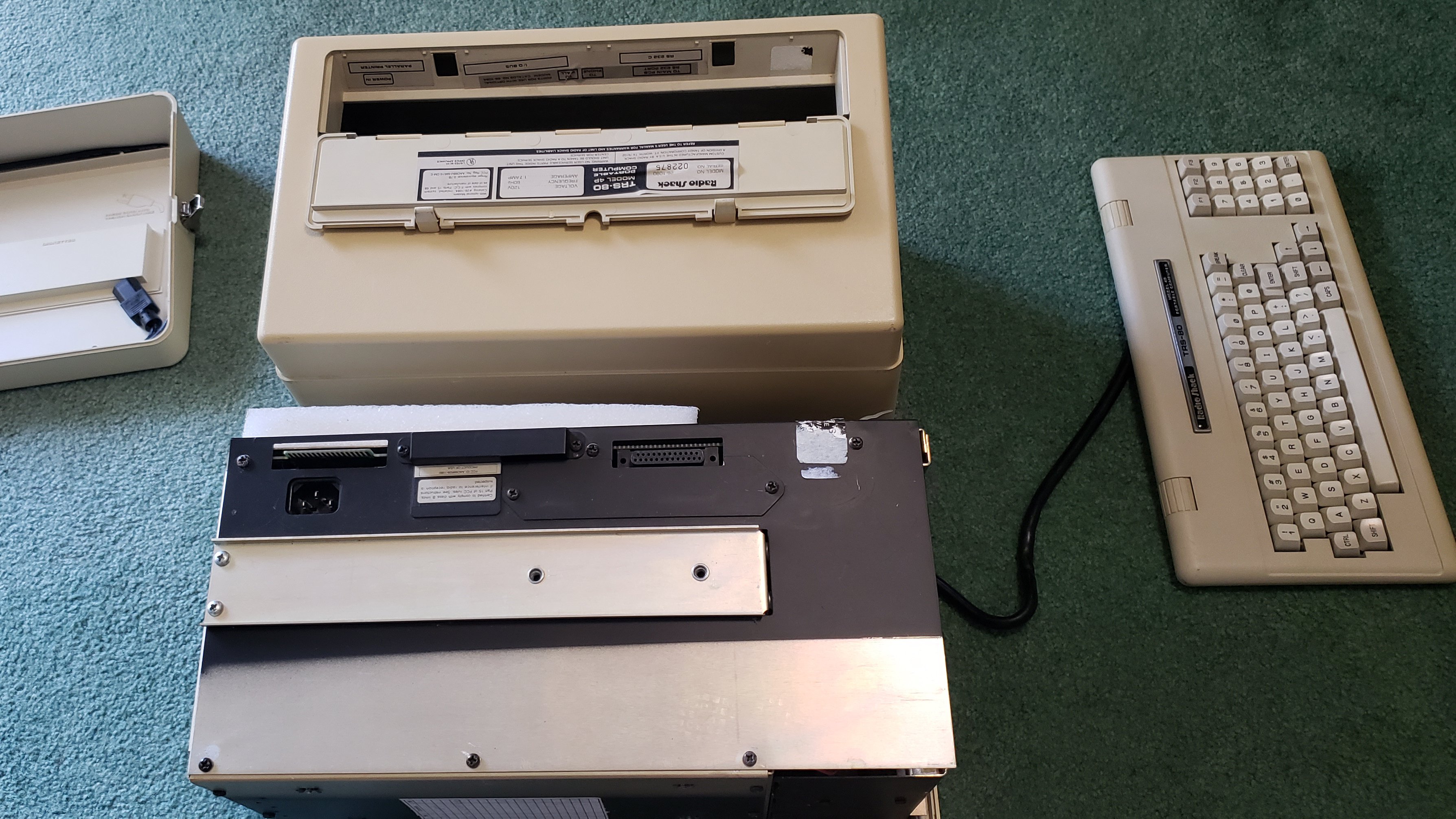
1A)
Remove the front cover, if you still have one.
1B)
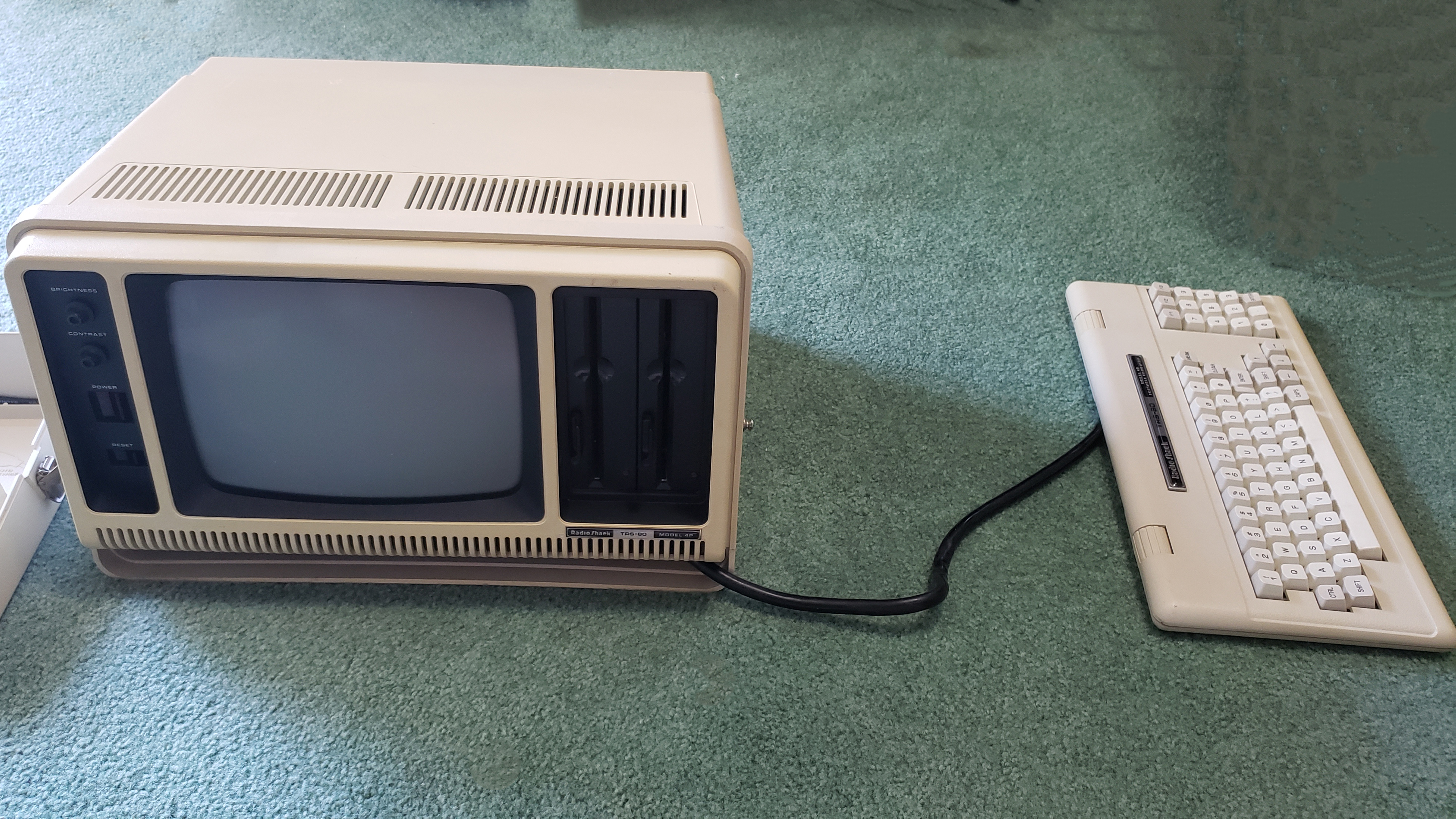
Put the keyboard out of the way.
1C)
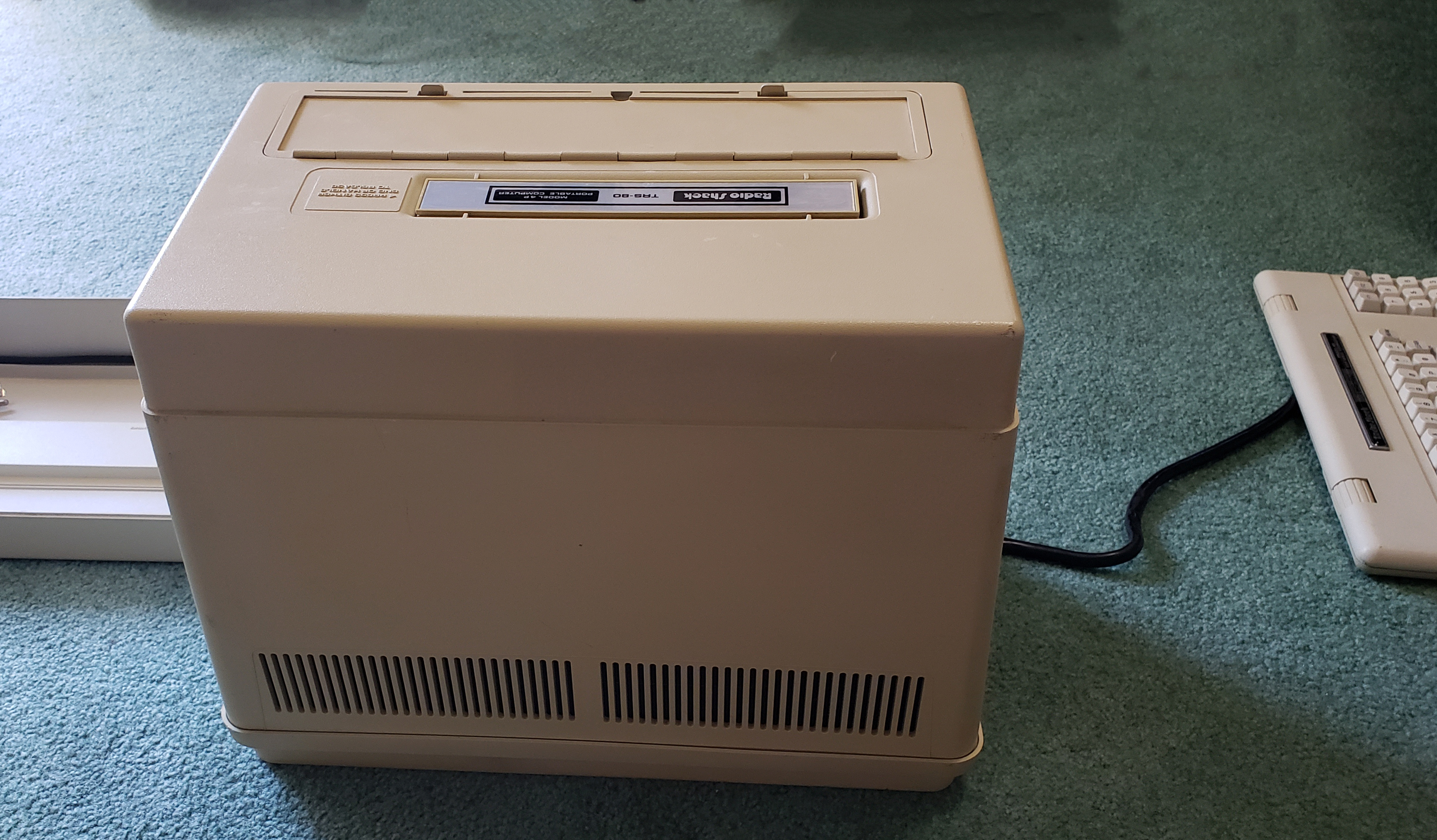
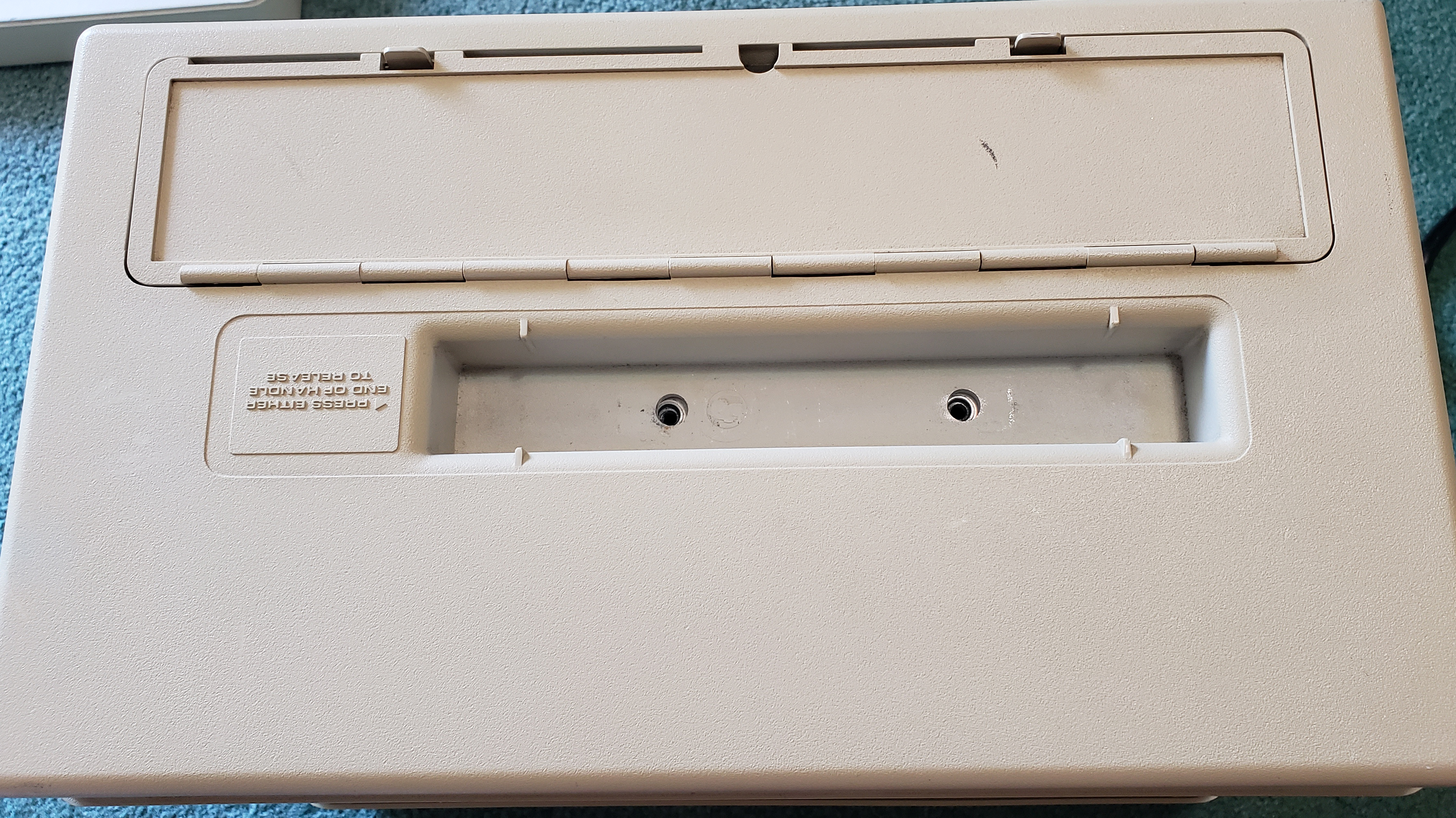
Put the Model 4P face down on a soft surface.
1D)
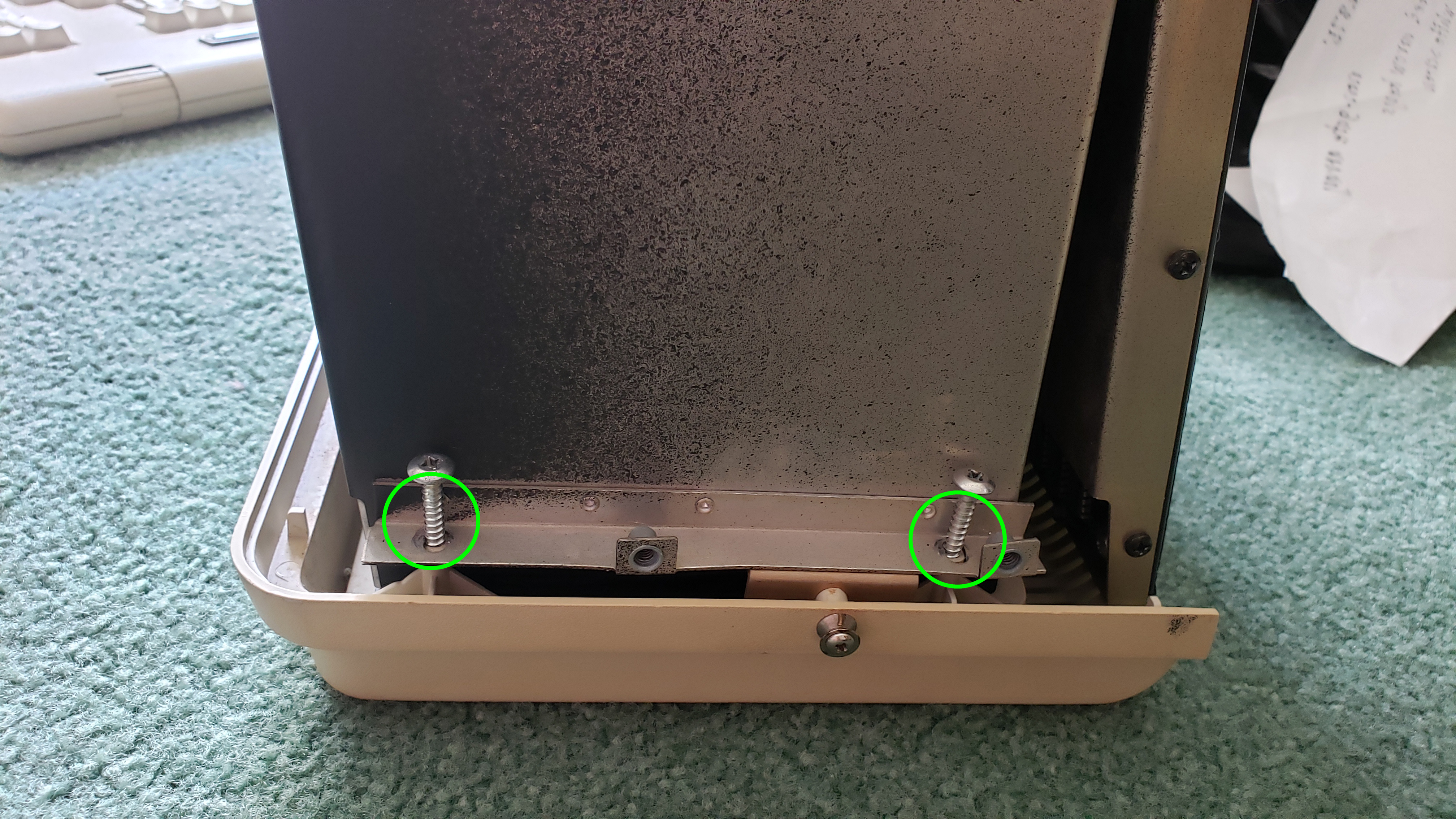
Remove the two screws on left and right side.
1E)
Lift the handle and remove the two screws which are now exposed.
1F)
That should be it for the outer case, so lift the outer case.
1G)
Unscrew the 8 screws on the top of the 4P.
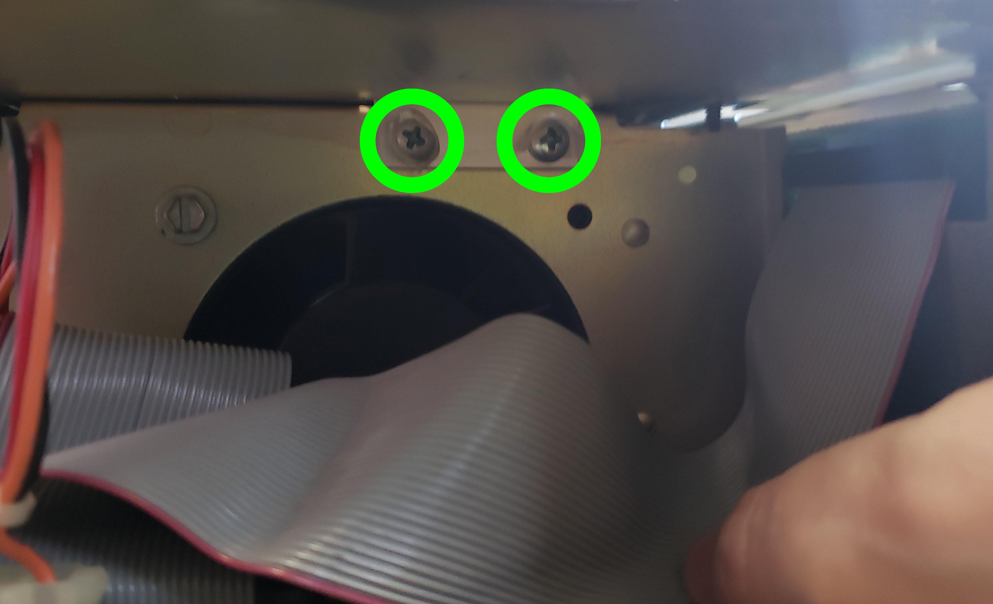
1H)
Unscrew the 2 screws above the floppy cable.
1I)
Remove the top and put it aside.
That opens the 4P. What you should do next depends on what you are trying to do!
If you are trying to swap the power supply …
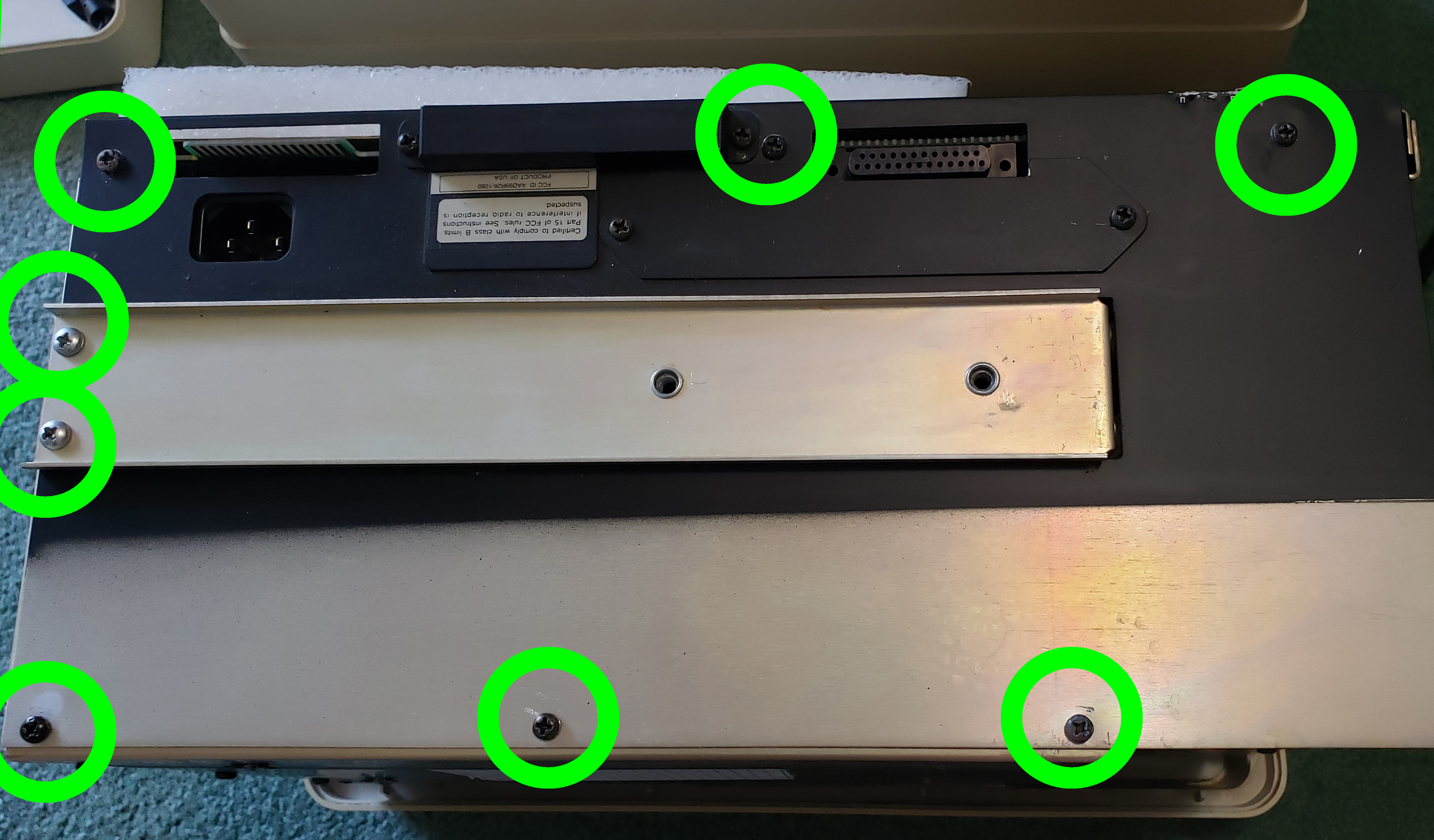
2A)
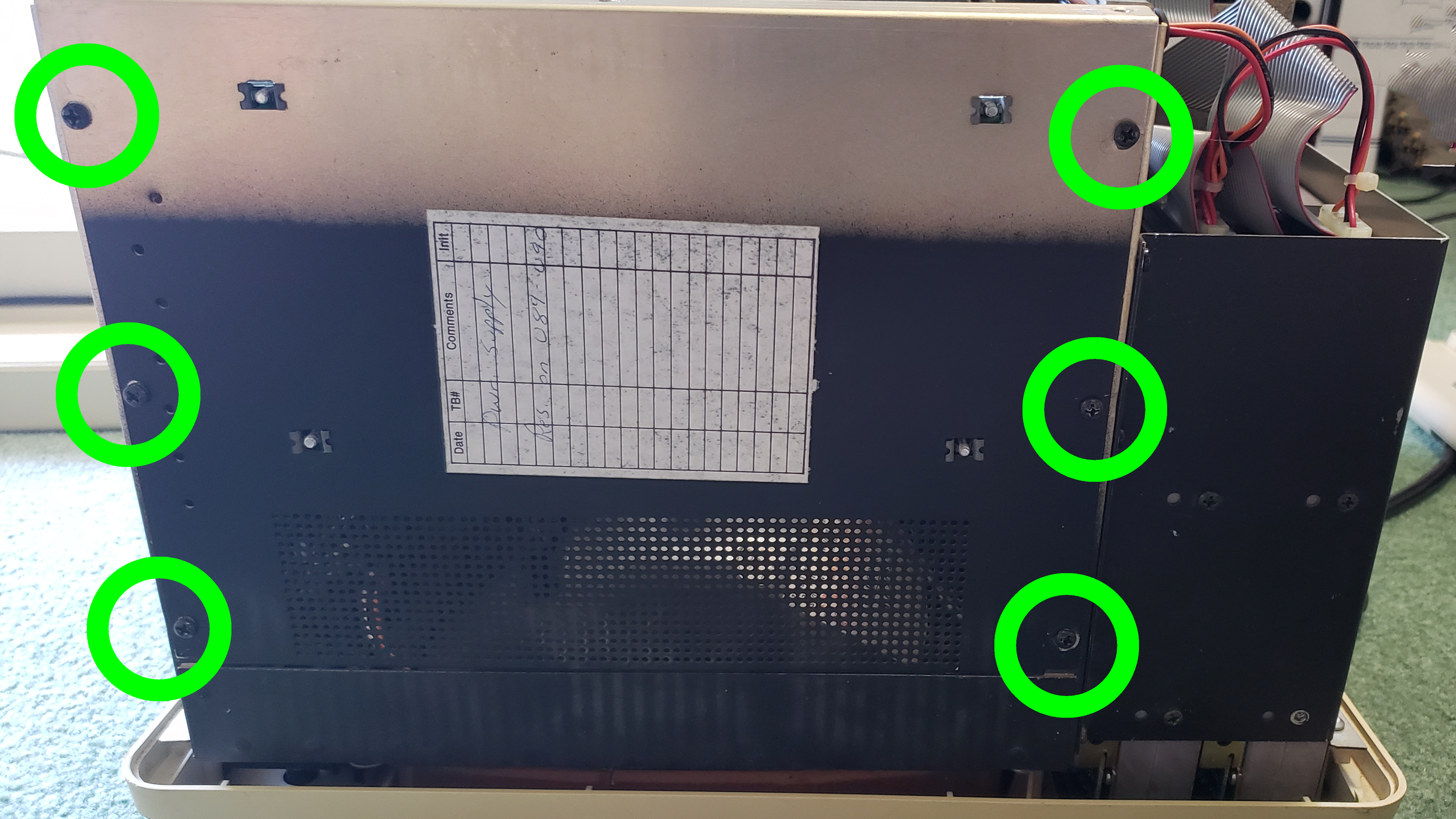
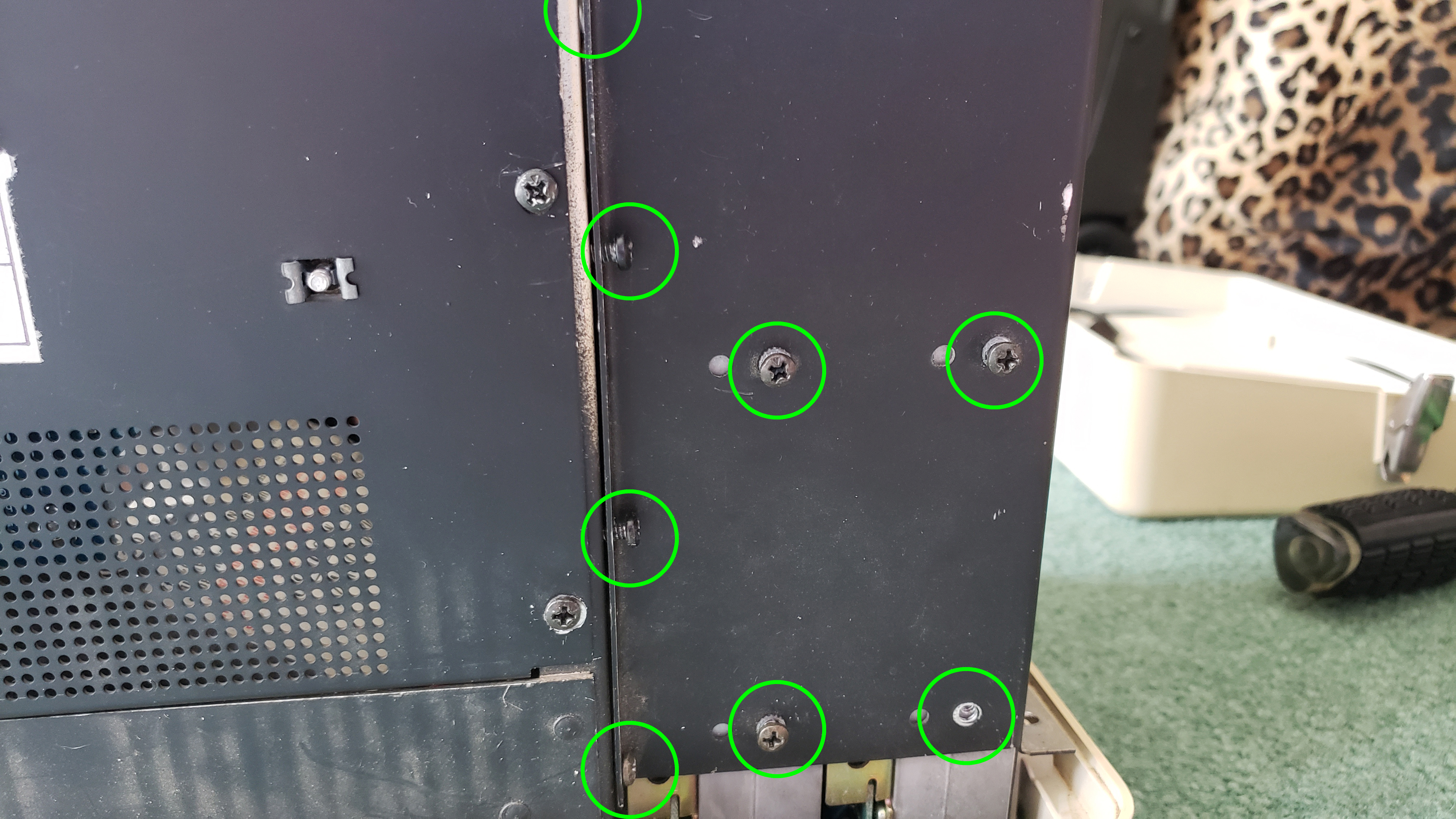
Unscrew the 6 screws on the side which would be the top of the 4P.
2B)
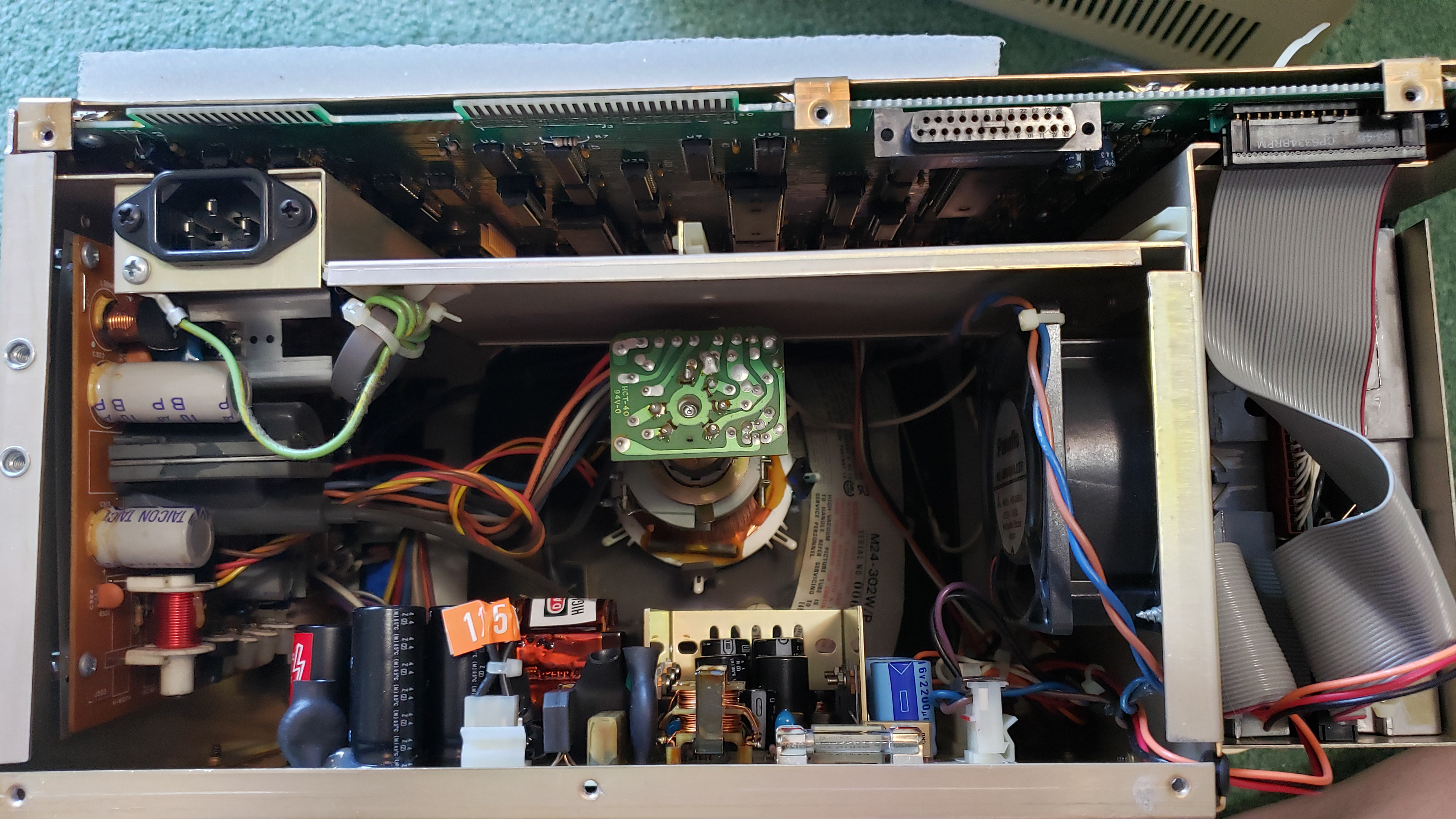
Carefully open the side you just unscrewed to expose the power supply.
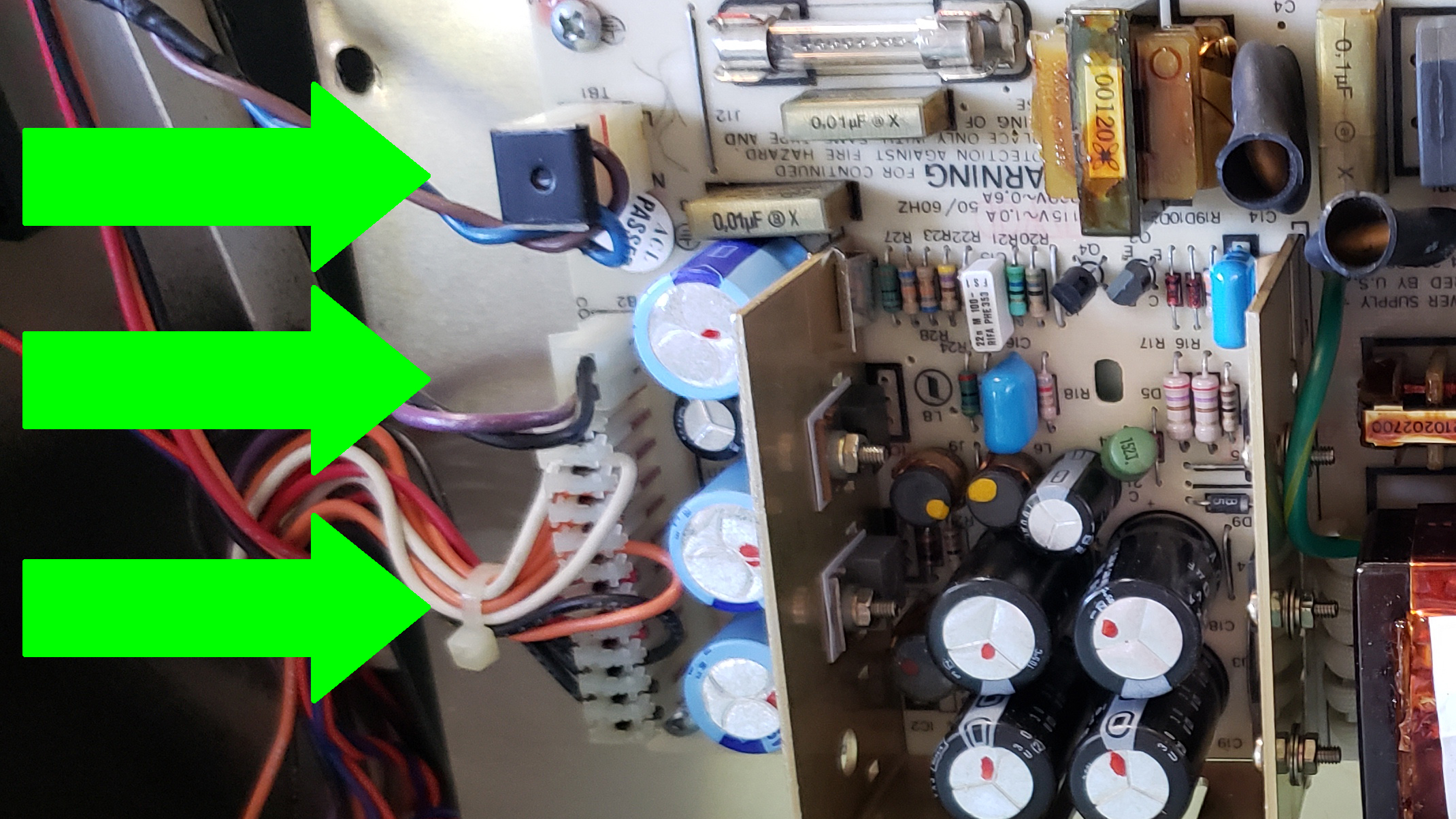
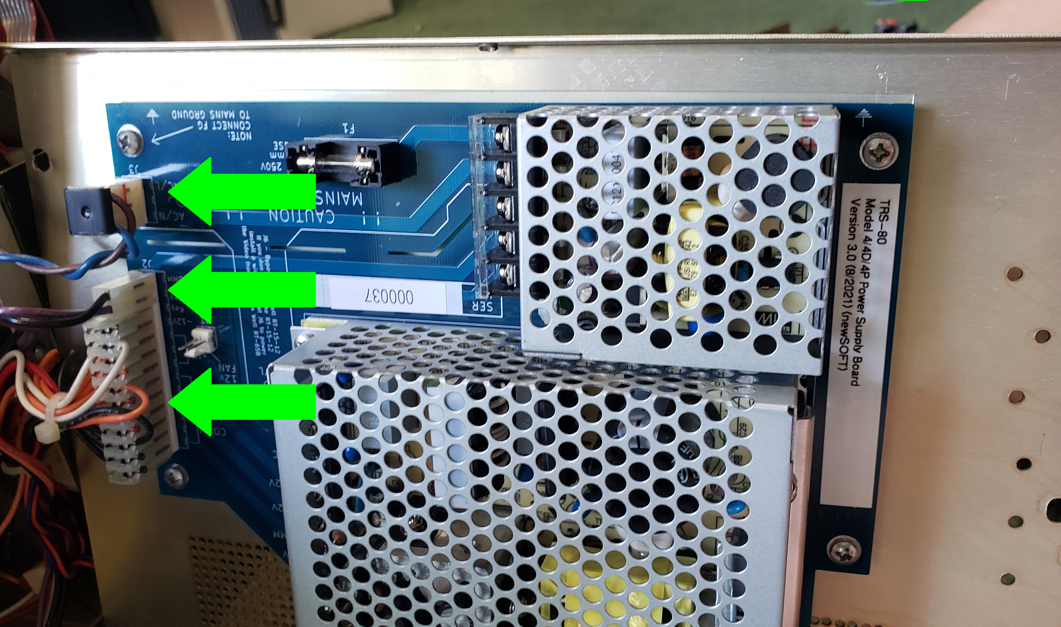
2C)
Unhook the three connectors in the front on the left (and remember where each was, and in what direction each cable was, for reassembly). You will need to hold up the lip to remove the middle connector.
2D)
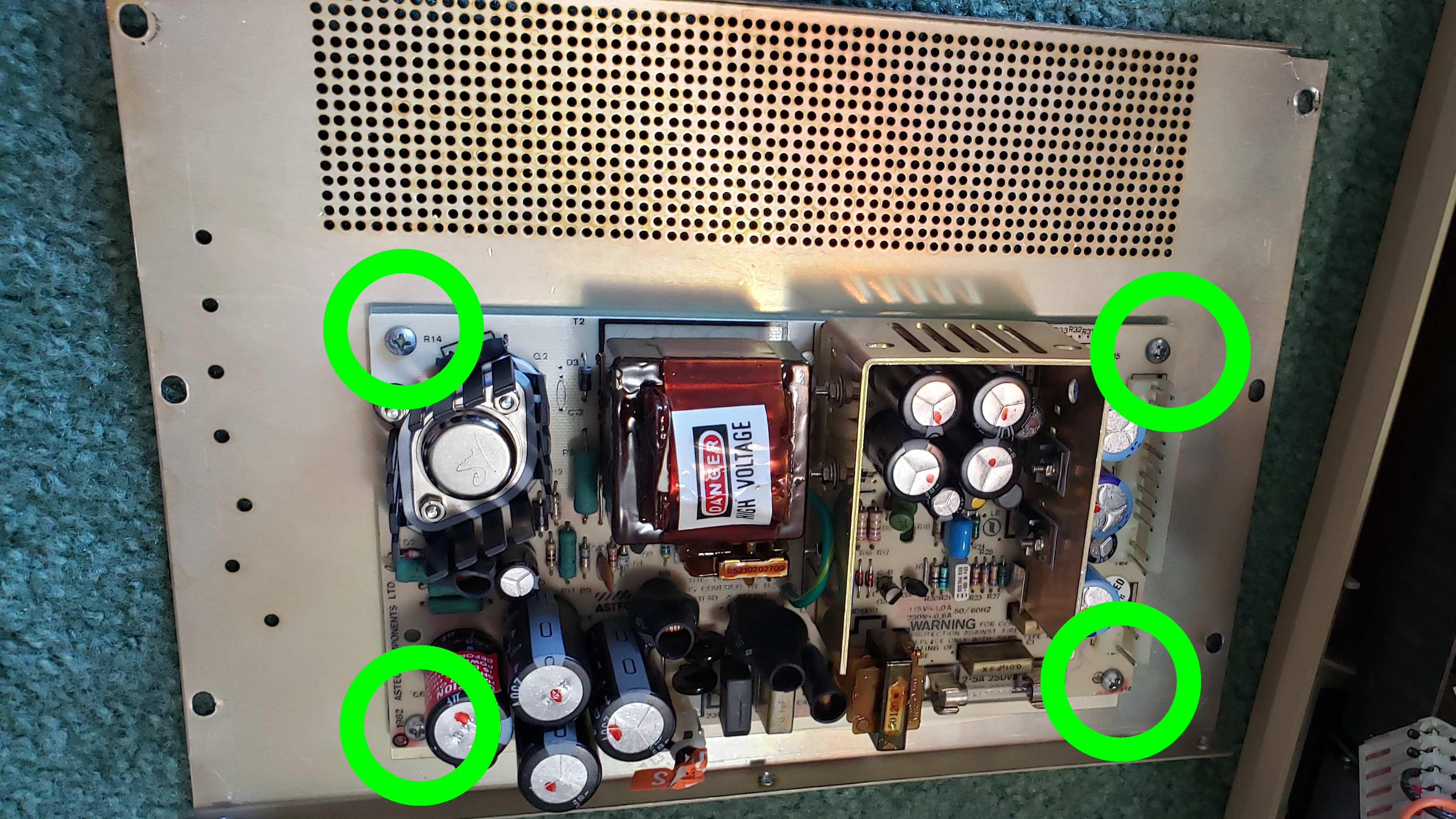
Lay the panel on the ground and unscrew the 4 screws holding down the power supply.
2E)
Screw in the new power supply.
2F)
Hook up the three connectors in the same positions they were when you removed them.
2G)
Replace and affix the panel with the powers supply.
2H)
Replace and affix the top panel.
If you are trying to swap the disk drives …
3A)
Unscrew the two screws holding the drive bay to the case.
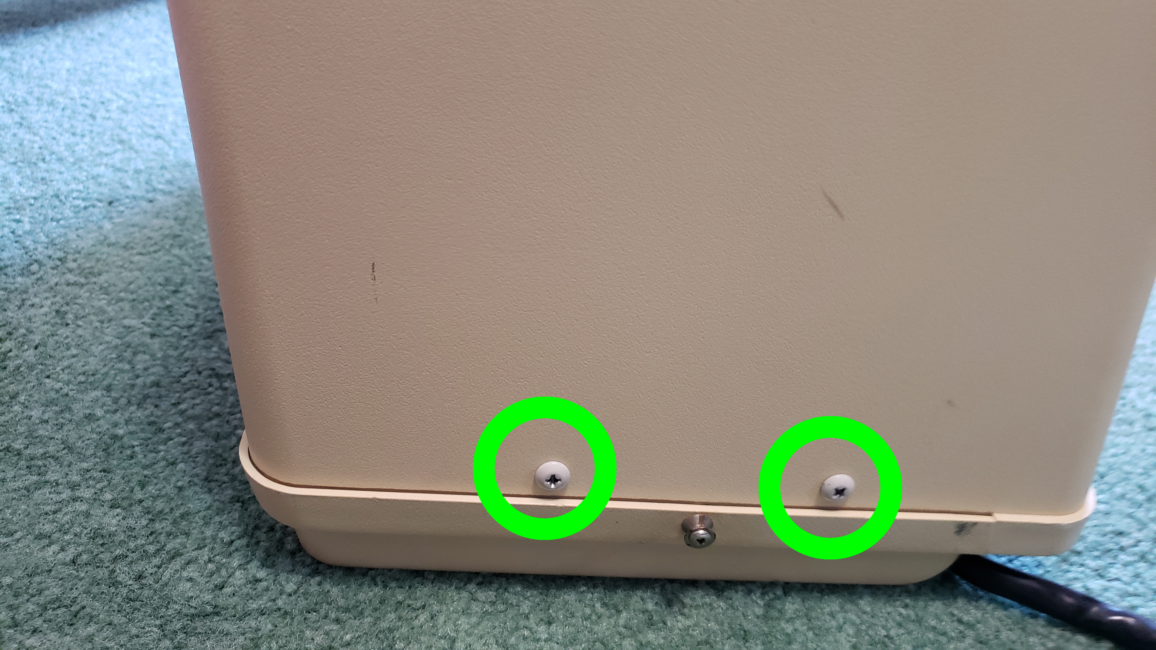
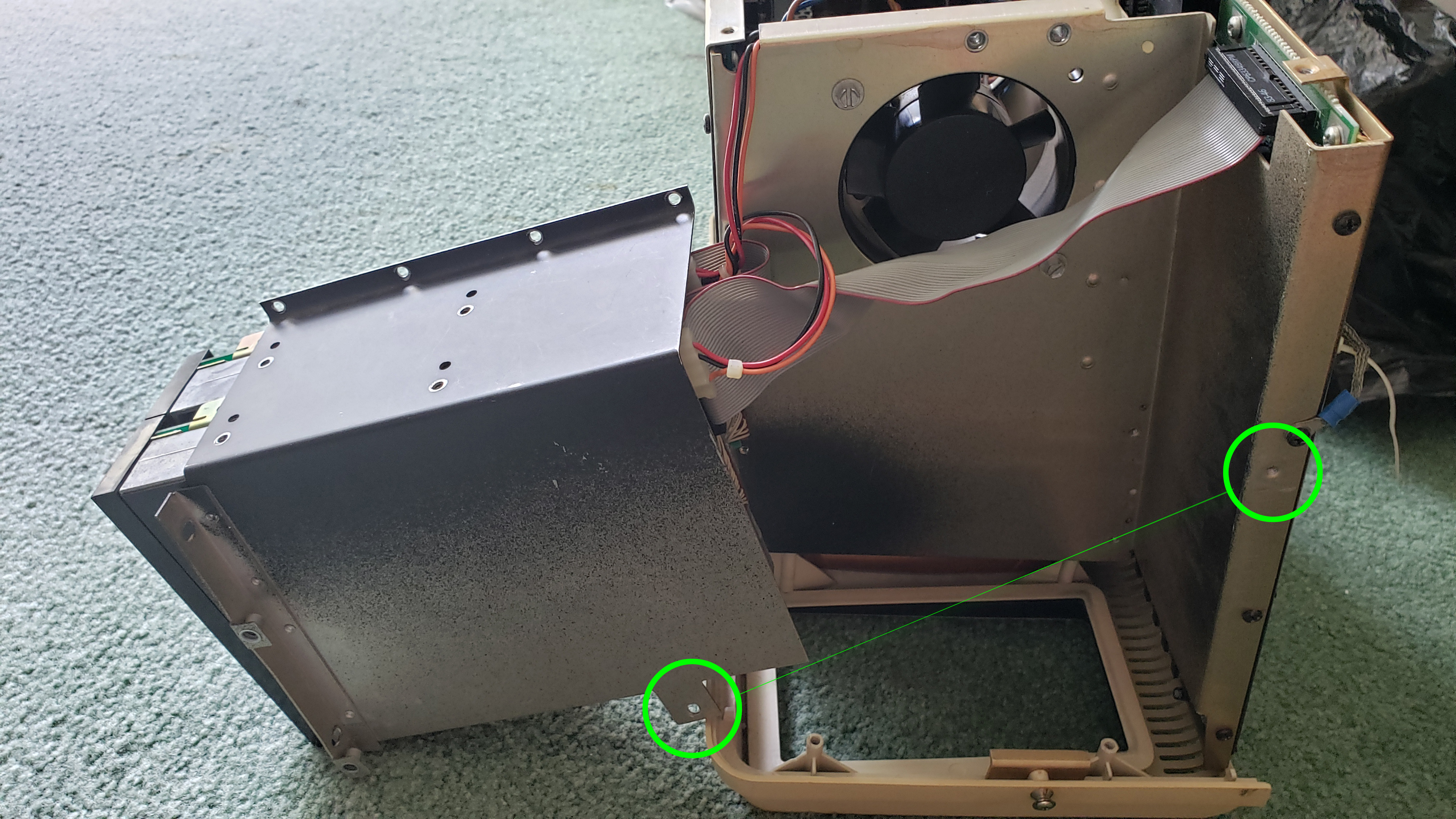
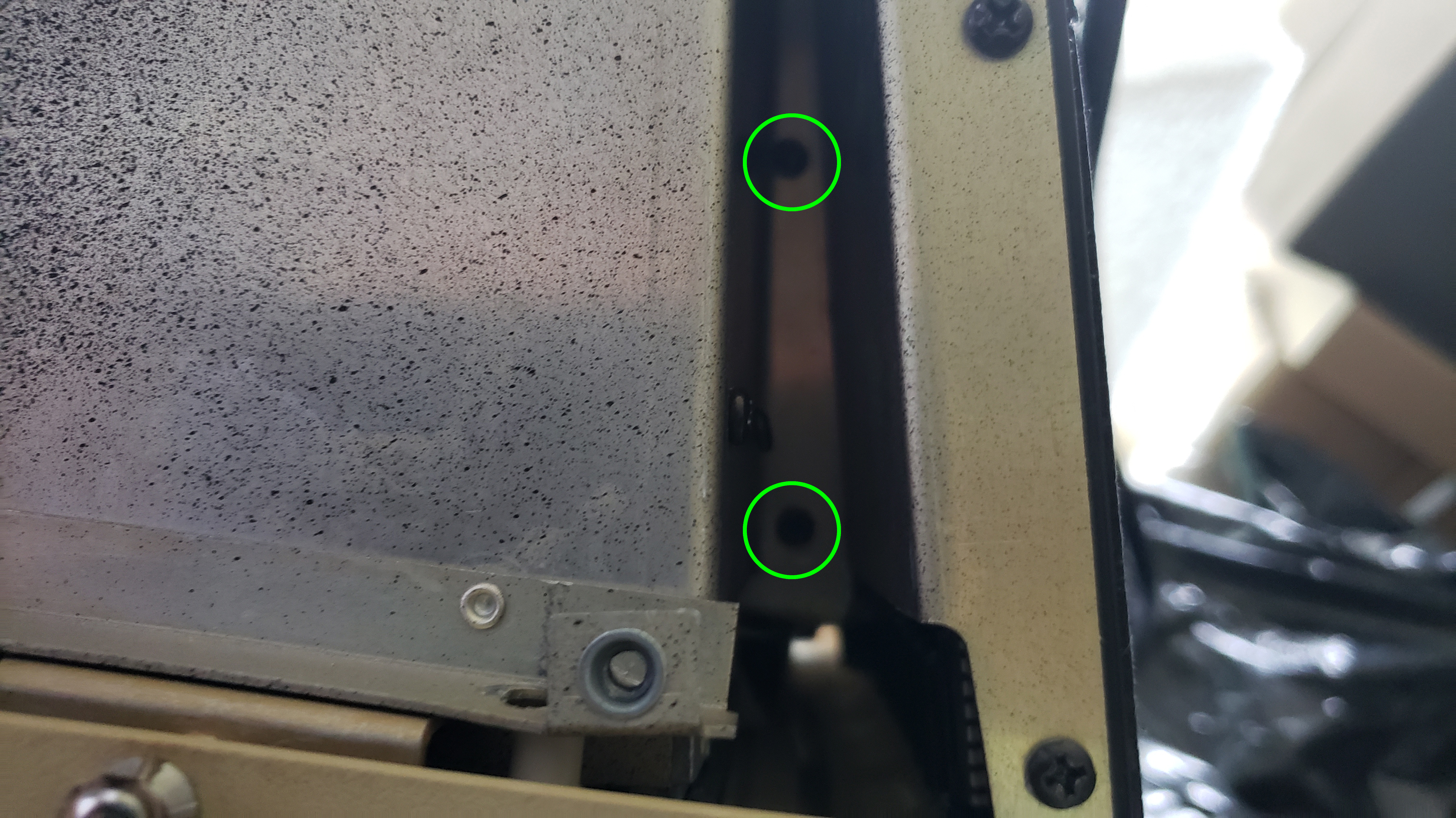
3B)
There is a screw to the rear holding the bay to the case, unscrew that as well. There was no screw in my case so I neglected to take a picture. So … the picture is the same picture below but with the two holes circled.
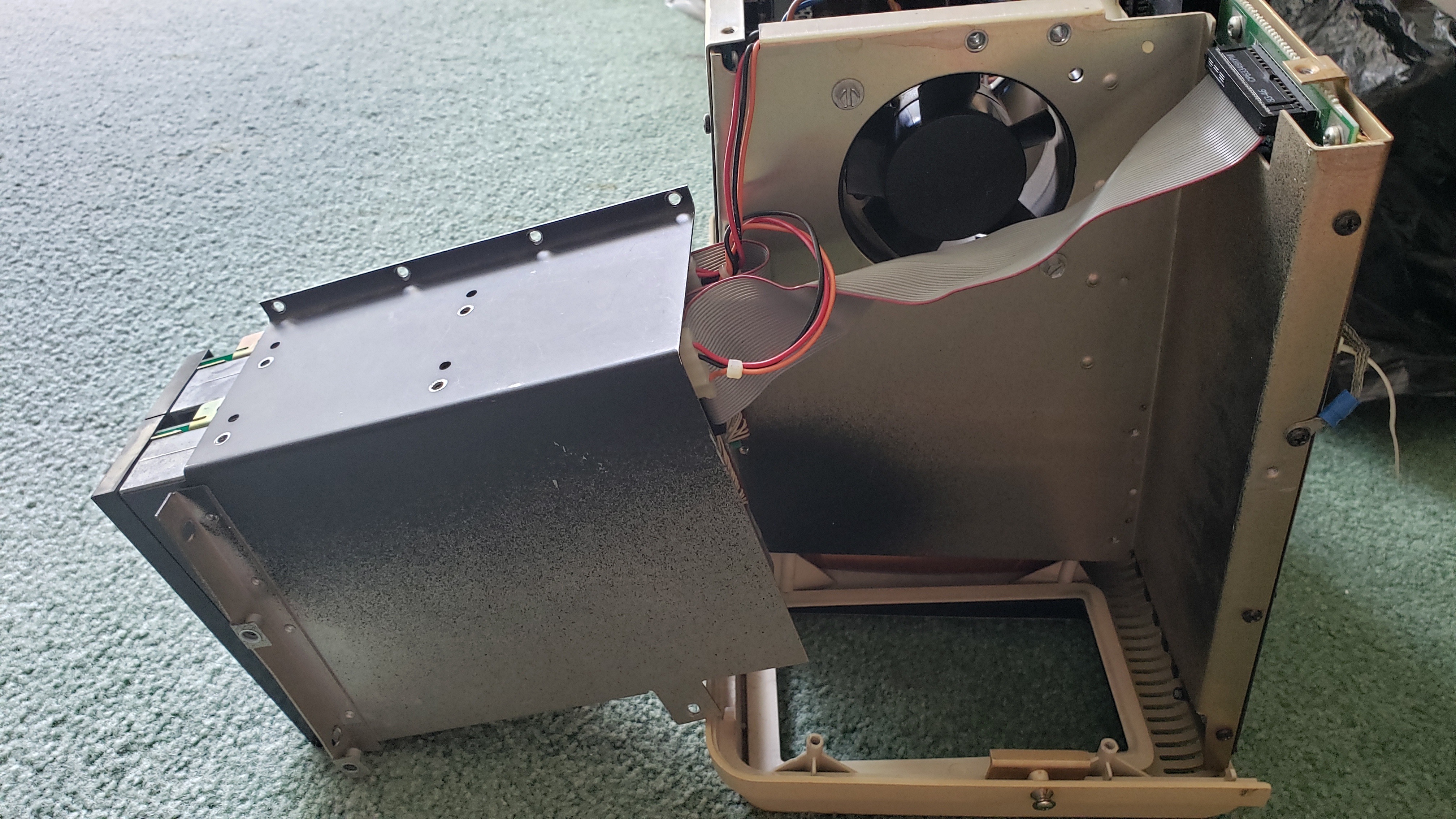
3C)
Unscrew all of the scres holding the drive bay to the internal supports. There may be additional screws that are not visible in this picture.
3D)
Unscrew the two screws to the right of the drive bay. They are WAY far back; but I found that scotch tape on the head of a screwdriver works well, and if they fall — so be it, just tilt the case.
3E)
The drive bay should easily come out.
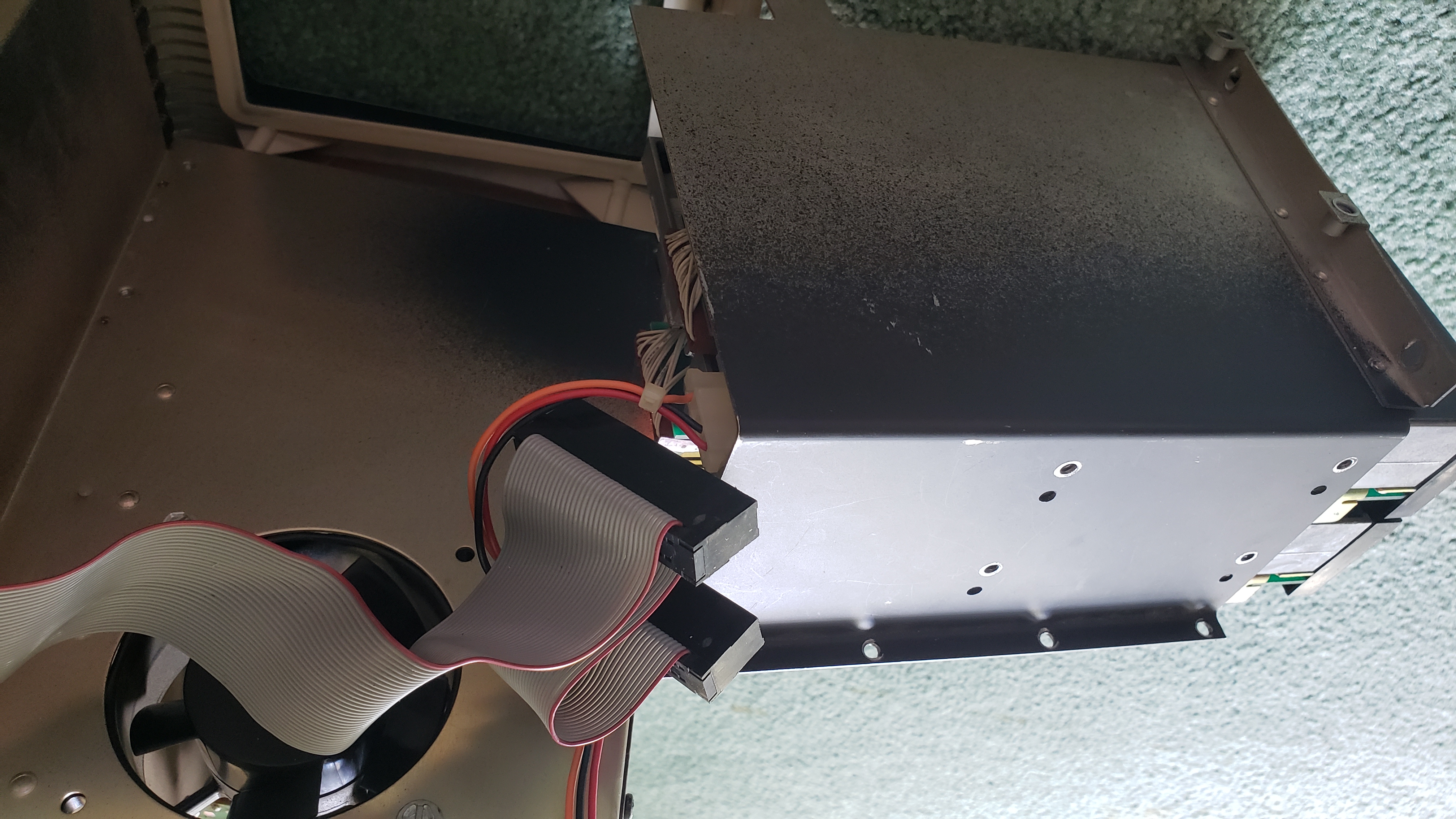
3F)
Remove the ribbon cable headers and the power cables.
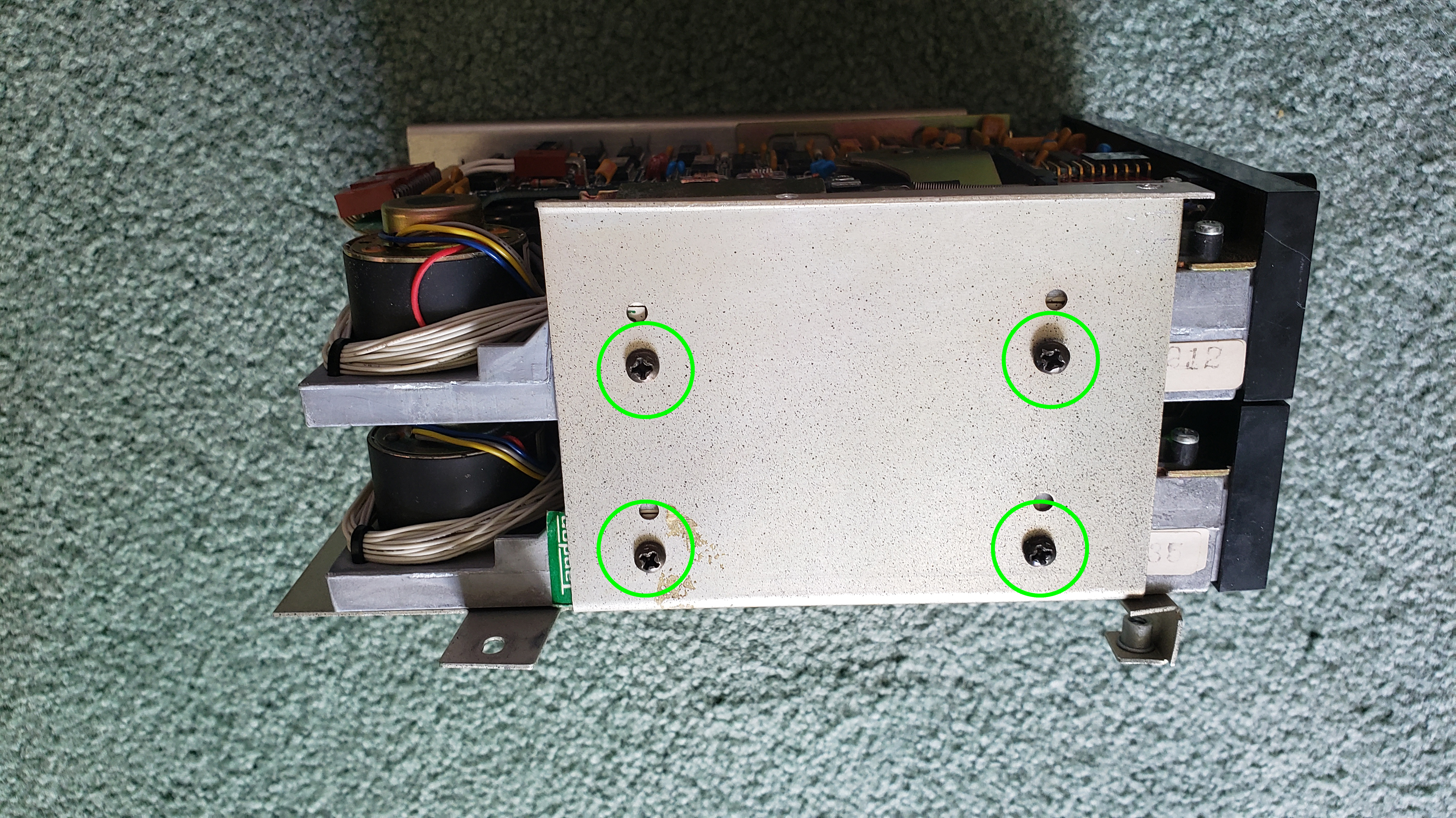
3G)
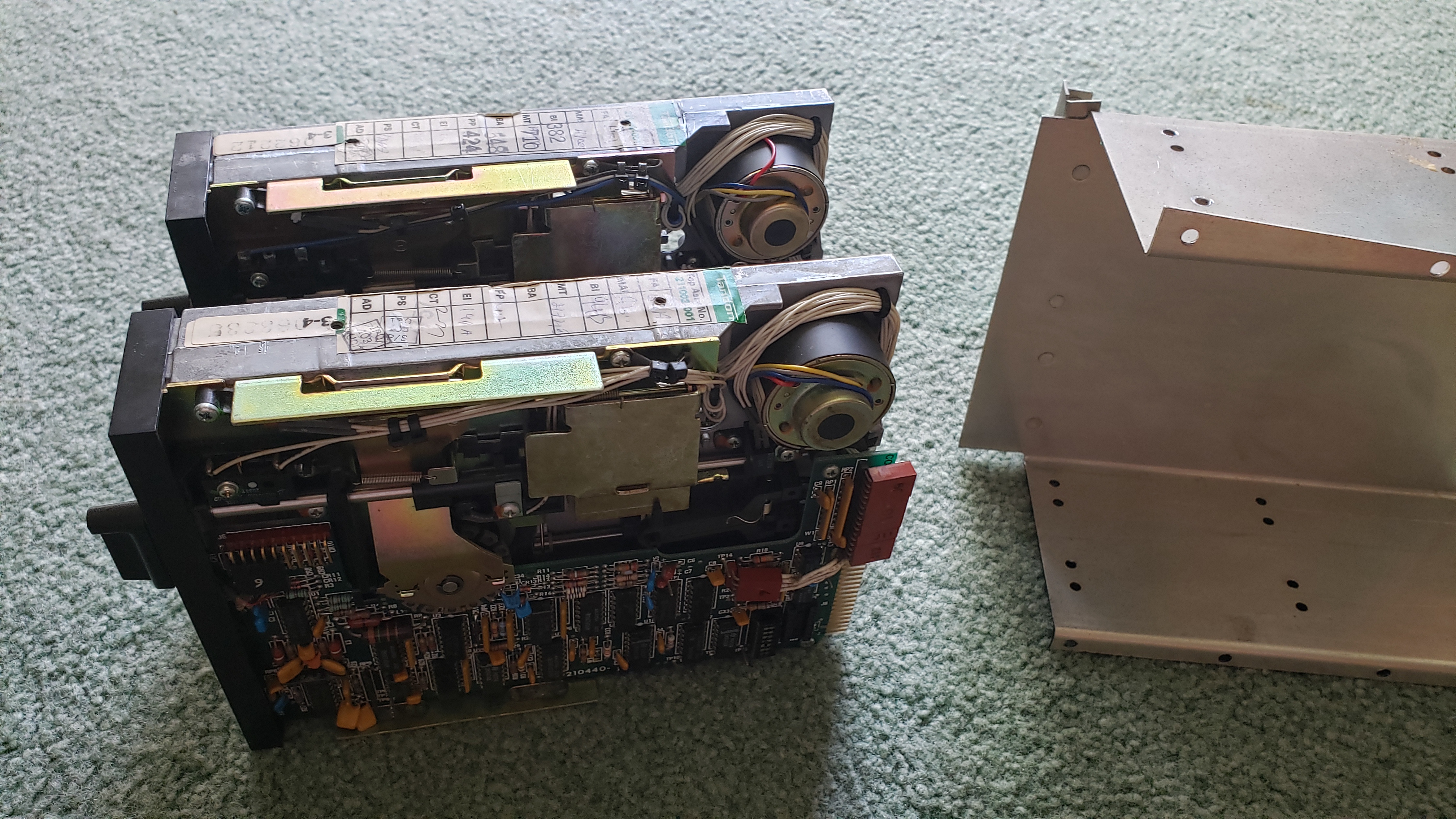
With the drive bay free, unscrew the screws holding the disk drives in place.
3H)
Your drives are now unhooked