Introduction
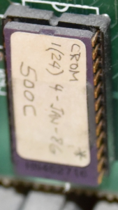
When Frank Durda IV passed away, his wife provided his collection to various archivists in the TRS-80 community. A Model 4 in that collection had a ROM which was under development by Frank and was never released to the public. That ROM had a “1(24) January 1986” label. This page is a disassembly of that ROM (and the other Model III ROM pages have been updated to account for Franks changes as alternative code), noting that the following are my findings:
- Since the Model III ROM tried to stay as close to the Model I ROM as possible, legacy bytes were still present in unused areas. Frank NOP’d them all.
- Moved as much code as possible from the end of the Model III ROM into the beginning of the Model III ROM. This was assisted by moving the PRINT SCREEN code out and by replacing a hidden name of “RON” in the code with the “CASS?” prompt. There were a bunch of changes in 0000H-0FFFH to accomplish this.
- Freed over 300 bytes in the 3000H-37FFH range by removing all the code which set out the keyboard map/translation tables and the printer translation table. He used bit manipulation instead of table lookups.
- Raised the base address for a SYSTEM cassette to be 42E8H instead of 4288H which stopped the SYSTEM tape from overwriting a LOT of Model III DOS RAM locations.
- Fixed 2 Bugs in the Model III ROM:
- Hitting BREAK at the filename inquiry of a SYSTEM command would reboot a Model III due to a bug in 02C3H-02C5H. This ROM returns to the READY prompt.
- Fixing a failure to tag an instruction as DATA because a byte was written to the wrong memory location (1BC1-1BC3, 1BDC-1BDE, and 1C67-1C69). This fix was the only change he made between ROM Address 1000H and 2FFFH
- Implemented code at 304BH to permit a boot from a Network 4 Controller which seem to be accessed by answering a number at the CASS? prompt other than 3 or 5.
- Implemented code at 316AH to permit a boot from a Hard Drive.
- Implemented code at 379CH which addressed hardware sitting at ports 30, 32, 33, 38, and 39
- Hid his initials in the ROM C
- Really streamlined some code to make all the above fit. Examples would be that if a routine needed to output a 0 to some ports and then a 1 to others, he would do those in that order with a BUMP or a XOR, or using the opcode LD (HL),00H instead of loading A with 0 first. He also broke out a few new memory addresses where he stored stuff.
3000 – Jump Table.
JUMP to 325CH for a SLOW tape header write.
3003
JUMP to 3299H for a FAST tape header write.
JUMP to 3272H for a SLOW tape header read.
JUMP to 32D8H for a FAST tape header read.
JUMP to 31C0H for Cassette OFF.
JUMP to 31D1H for Cassette ON.
JUMP to 30C3H for Warm Boot.
JUMP to 30A2H for Bootstrap.
JUMP to 35C3H for Maskable Interrupt Handler.
301B
JUMP to 3601H for RS-232 Initialization.
JUMP to 364AH for RS-232 Input.
3021
JUMP to 3676H for RS-232 Output.
JUMP to 338CH for Keyboard Input.
JUMP to 3781H for Print Screen Routine.
JUMP to 31F7H for Print# Processing
JUMP to 3739H for a routine which parses whether the current instruction on a the current line is in quotes.
JUMP to 37EAH for a routine which allows BASIC TIMES (DATE$+” “+TIME$)
3033
JUMP to 35BCH to put the DATE onto the upper right hand corner of the screen.
3036
JUMP to 35A1H to put the TIME 10 characters from the upper right hand corner of the screen.
JUMP to 4049H which is the NMI RST Vector
303C-303F – Frank Durda IV’s Initials
303C-303F
“FDIV”
Frank Durda IV’s Initials
3040-3047 – No Location Jumps Here. This may have been a Frank Durda Embedded Serial Number of 98 36 C3 7D 30 C3 6A 37.
3040
SBC A,B
Subtract Register B and the CARRY FLAG from Register A.
3041
LD (HL),C3H
Put a C3H into the memory location pointed to by (HL)
3043
LD A,L
Let Register A = Register L
3044
If the SBC command in 3040H did not produce a CARRY FLAG, JUMP to 3009H
3045
** Z-80 TRICK ** – I guess Frank wanted to do one! If you jump to 3045H you are jumping into the middle of the instruction at 3044H, but that turns into this JUMP.
3046
LD L,D
If the SBC command in 3040H did produce a CARRY FLAG, Let Register L = Register D.
3047
SCF
Set the CARRY FLAG.
3048 – This subroutine is called by the print routine when a LINE FEED or CARRIAGE RETURN is the current character.
304B – Part of the Network 4 Controller Boot – GOSUB’ed by 3076H and 30ECH
304B
LD A,(3810H)
Put the contents of 3810H into Register A.
NOTE: 3810H is the row of the keyboard matrix holding 0 through 7.
304E
BIT 3,A
Check Bit 3 of A. Bit 3 of 3810H will be on only for the 3 key.
3050
JP NZ,34E5H
If the key pressed is not a 3 then JUMP to 34E5H
3053
AND 10H
MASK A against 10H (Binary: 0001 0000) to leave only Bit 5 so as to check to see if a 5 key was pressed.
3055
If a 5 key was pressed, JUMP to 028DH to check for a BREAK key.
3058
POP BC
Restore the STACK into Register Pair BC
3059
XOR A
Zero Register A and clear all flags.
305A
OUT (D1H),A
Output the contents of Register A to Port D1H.
305E
OUT (D3H),A
Output the contents of Register A to Port D3H.
3060
LD BC,00D0H
LET BC = 00D0H. This is setting us up for B=0 as a counter, and C=D0H as a port.
3063
LD HL,7000H
LET HL = 7000H (Decimal: 28672)
3066
PUSH HL
Save the value in HL to the STACK
INIR
This command takes a byte from Port C (D0H) and writes it to the memory location pointed to by (HL). HL is then incremented, and B is decremented. If B is not zero, this operation is repeated. Interrupts can fire during this command.
3069
DEC A
Decrement A by 1.
306A
If Register A is NOT ZERO then JUMP to 3067H.
306C
LD HL,7300H
If we are here, then A was ZERO, so lets LET HL = 7300H, which is the memory location of the NETWORK 4 ROM.
306F – This tests to see if the first byte of the RAM address to pass control to (4300H for Floppy or Hard Drive, 7300H for Network 4) is a FDH. If not, we have a problem and RETURN, with NZ set. Ohterwise, Bump the starting memory address beyond that first byte, and JUMP to it to pass control to that BOOT CODE.
306F
LD A,(HL)
LET A = the memory contents of (HL).
3070
CP FDH
Compare Register A against FDH. Results:
- If A=FDH it sets the ZERO FLAG
- If A<FDH then the CARRY FLAG will be set
- if A>=FDH then the NO CARRY FLAG will be set.
3072
RET NZ
If A is NOT FDH then RETURN out of the routine.
3073
POP DE
If we are here then A = FDH, so restore the STACK back into Register Pair BC.
3075
JP (HL)
JUMP to the memory location held in (HL).
304B – Part of the Network 4 Controller Boot – This was JUMPed to from 30EAH. This routine appears to process the CASS? answer, but beyond just H and L.
3076
GOSUB to 304BH, above.
LD HL,0075H
HL = 0075H. 30EFH and 3100H jump here, but it can also be a pass through.
307C
PUSH HL
Save HL to the STACK.
LD HL,05D1H
HL = 05D1H.
NOTE: 05D1H is the location of the “CASS?” prompt.
| 3080
GOSUB down to 309CH (which GOSUBs to 021BH [to display the message pointed to by HL] and then JUMPS to 0049H)
| 3083
GOSUB to 0033H to display the character held in Register A at the current cursor position.
| 3086
SUB 4CH
SUBtract 4CH (ASCII: “L”) from Register A.
| 3088
LD (4211H),A
Set the Model III Cassette Baud by putting A (which is either 0 if “L” was hit, something else if anything else was hit) into (4211H).
| 308B
If the subtraction set Register A at zero (meaning “LOW” speed was selected at the CASS? prompt, JUMP down a few instructions to 3092H to display the L, restore AF from the STACK, and RETURN.
| 308D
CP C1H
If we are here, a key response other than
L was entered at the “CASS?” prompt, so lets COMPARE Register A against C1H. Results:
- If A=C1H it sets the ZERO FLAG
- If A<C1H then the CARRY FLAG will be set
- if A>=C1H then the NO CARRY FLAG will be set.
| 308F
RET Z
If the modified Register A was C1H then RETURN.
| 3090
CP FCH
If we are here, then Register A was not 0 and was not C1H, so lets COMPARE Register A against FCH. Results:
- If A=FCH it sets the ZERO FLAG
- If A<FCH then the CARRY FLAG will be set
- if A>=FCH then the NO CARRY FLAG will be set.
PUSH AF
Save Register Pair AF to the STACK so we can use A in the next 2 instructions.
| 3093
LD A,0DH
LET A = 0DH (ASCII: Carriage Return).
| 3095
GOSUB to 0033H to display the character held in Register A at the current cursor position.
| 3098
POP AF
Restore AF from the STACK
| 3099
LOOP back to 307DH until the ZERO FLAG is set.
309C – This subroutine will display the message held in HL and then JUMP to the KBWAIT (Wait for Keypress) Routine.
309C
GOSUB to 021BH to display the message pointed to by HL.
309F
JUMP to 0049H which RETURNS as soon as any key on keyboard is pressed, with Register A holding the ASCII value for character pressed.
30A2 – This is a VECTOR JUMP from 3015H – It resets all the ports, sets the interrupt to jump to 4046H, moved 76 bytes from 36AAH to 4000H, and reads disk sectors into 4000H+ until the interrupt fires.
30A2
IM 1
Set the INTERRUPT MODE to 1.
30A4
LD SP,407DH
Set up stack pointer to point to 407DH.
30A7
OUT (E4H),A
Send the value held in Register A to Port E4H.
NOTE: Port E4H is the Non-Maskable Interrupt Latch. Sending a 0 to E4 will turn off all Non-Maskable Interrupts.
30AC
LD HL,37E6H
Let HL = 37E6H which will be the memory location that Port 89H feeds.
30AF
LD A,0FH
Let A = 0FH (Decimal: 15) as A will be a counter
30B1
LD C,89H
Let C = 89H as the Port which will feed (HL)
OUT (88H),A
Send the value held in Register A to Port 88H.
NOTE: Port 88H is the CRT Controller Control Register..
| 30B5
OUTD
This command takes the byte held in the memory location pointed to by HL and writes it to Port C. HL and B are then both decremented.
+ 30B8
If A is still positive, then LOOP back up to 30B3H.
30BD
OUT (ECH),A
Output 38H (Binary: 0011 1000) to Port ECH.
NOTE: Port ECH stores miscellaneous controls.
- Bit 3: Alt. char. [0 = disable, 1 = enable]
- Bit 4: I/O bus [0 = disable, 1 = enable]
- Bit 5: Video waits [0 = disable, 1 = enable] � Model 4 ONLY
- Bit 6: CPU clock speed [0 = 2 mhz, 1 = 4 mhz]
30C1
OUT (E0H),A
OUTput 04H (Binary: 0000 0100) to Port E0H.
NOTE: Port E0H stores the Maskable Interrupt. By sending Bit 2 HIGH, that chooses 4046H as the Maskable Interrupt Jump
30C3 – This is in the middle of the machine setup routine – While this is a pass through to set up the machine / warm boot, it is also a jump point for a failure to boot from anything AND is a VECTOR jump from 3012H.
30C5
OUT (F4H),A
OUTput 81H (Binary: 10000001) to Port F4H.
NOTE: Port F4H is the Floppy drive select and options register. For OUTPUT:
- Bit 0: Drive 0 Select
- Bit 1: Drive 1 Select
- Bit 2: Drive 2 Select
- Bit 3: Drive 3 Select
- Bit 4: Side Select (0 = Select Side 0, 1 = Select Side 1)
- Bit 5: Write Precompensation (0 = Disable WP, 1 = Enable WP)
- Bit 6: Wait State Generation (0 = Disable WSG, 1 = Enable WSG)
- Bit 7: Density Select (0 = Single/FM, 1 = Double/MFM)
30C7
OUT (E8H),A
OUTput 81H (Binary: 10000001) to Port E8H.
NOTE: Port E8H is the RS-232 Status Register and Master Reset. Outputting ANYTHING to this port will reset the RS-232.
30CB
OUT EAH,A
OUTput 6FH (Binary: 0110 1111) to Port EAH.
NOTE: Port EAH is the RS-232 UART Control Register/Status Register. For output:
- Bit 0: Data Terminal Ready
- Bit 1: Request to End
- Bit 2: Break
- Bit 3: Parity Enable
- Bit 4: Stop Bits
- Bit 5: Select
- Bit 6: Word Length
- Bit 7: Parity (0=Odd, 1=Even)
30CD
LD HL,36AAH
Let HL = 36AAH
30D0
LD DE,4000H
let DE = 4000H
30D3
LD BC,004CH
Let BC = 004CH (Decimal: 76 Bytes)
30D6
LDIR
Moves the byte from (HL) to (DE), then HL and DE are incremented, and BC is decremented until BC is zero. Interrupts CAN fire during this command.
30DA
OUT (F0H),A
Send 0CH (Binary: 0000 1100) to port F0H.
NOTE: Port F0H is the Floppy Disk Command/Status Register. 0000 1100 is the command to RESTORE (0000), LOAD HEAD AT THE BEGINNING (1), VERIFY ON (1), 6ms STEP (00).
30DC
LD DE,41E2H
LET DE = 41E2H
30DF
LD C,46H
LET C = 46H (Decimal = 70).
30E1
LDIR
Moves the byte from (HL) to (DE), then HL and DE are incremented, and BC is decremented until BC is zero. HL is 365EH. Interrupts CAN fire during this command.
30E3
GOSUB to 3518H to initials the Port 84H settings
30E6
IN A,(F0H)
INput from Port F0H.
NOTE: Port F0H is the FDC Status port on input. Input Results:
- Bit 0: Busy
- Bit 1: Index/DRQ
- Bit 2: Track 0/Data Lost
- Bit 3: CRC error
- Bit 4: Seek error/Record not found
- Bit 5: If Reading, Record Type, if Writing, Write Fault/Head loaded
- Bit 6: Write Protect
- Bit 7: Not ready
30E8
LD C,A
Let Register C = Register A.
30EA
If A is ZERO (meaning that Port F0H was FFH), JUMP to 3076H
If A wasn’t ZERO, then GOSUB to 304BH
30EF
If the NOT ZERO flag is set, JUMP to 3079H.
30F1
IN A,(F0H)
INput from Port F0H.
NOTE: Port F0H is the FDC Status port on input. Input Results:
- Bit 0: Busy
- Bit 1: Index/DRQ
- Bit 2: Track 0/Data Lost
- Bit 3: CRC error
- Bit 4: Seek error/Record not found
- Bit 5: If Reading, Record Type, if Writing, Write Fault/Head loaded
- Bit 6: Write Protect
- Bit 7: Not ready
30F3
LD C,A
Let Register C = Register A.
30F4
BIT 2,A
Test Bit 2 of Register A. That Bit is for “TRACK 0 FOUND”.
30F6
If Bit 2 of Register A is LOW, then skip the next instruction and JUMP to 30F9H.
30F8
LD B,A
Let Register B = Register A
AND 81H
MASK Register A against 81H (Binary: 1000 0001) to keep only Bits 0 and 7, which would be BUSY and NOT READY.
30FB
DEC A
Decrement Register A by 1. By doing this, a Port 81H status of NOT BUSY and NOT READY will return a ZERO FLAG.
30FC
If the Decremented Register A is ZERO, then JUMP to back to 30ECH to keep polling the drive.
30FE
LD A,B
Let Register A = Register B
30FF
OR A
Set the Flags for Register A
3100
If A was ZERO, then JUMP back to 3079H to trigger the “CASS?” routine.
3104
LD A,C
Let Register A = Register C
3105
AND 98H
MASK Register A against 98H (Binary: 1001 1000) to keep only Bits 3, 4, and 7 (which are CRC ERROR, SEEK ERROR, and NOT READY).
3107
If none of those 3 errors are present, then JUMP to down to 314EH which tests for a Hard Drive.
3109
LD D,03H
If we are here, then we have either a CRC ERROR, SEEK ERROR, or NOT READY. Let Register D = 03H.
LD A,81H
Let Register A = 81H.
310D
OUT (F4H),A
OUTput 81H (Binary: 10000001) to Port F4H.
NOTE: Port F4H is the Floppy drive select and options register. For OUTPUT:
- Bit 0: Drive 0 Select
- Bit 1: Drive 1 Select
- Bit 2: Drive 2 Select
- Bit 3: Drive 3 Select
- Bit 4: Side Select (0 = Select Side 0, 1 = Select Side 1)
- Bit 5: Write Precompensation (0 = Disable WP, 1 = Enable WP)
- Bit 6: Wait State Generation (0 = Disable WSG, 1 = Enable WSG)
- Bit 7: Density Select (0 = Single/FM, 1 = Double/MFM)
310F
DEC A
Decrement Register A (so make Register A = 80H or 1000 0000.
3110
OUT (E4H),A
Send a Bit 7 HIGH to Port E4H.
NOTE: Port E4H is the Non-Maskable Interrupt Latch. Sending a Bit 7 HIGH to E4 will ENABLE INTRQ Interrupts.
3112
LD HL,313BH
LET HL = 313BH
3115
LD (404AH),HL
Put 313BH into (404AH) and (404BH)
311A
LD (4049H),A
Put C3H into (4049H).
NOTE: 4049H is the RST 0 NMI Vector.
311D
LD C,F3H
Let C = F3H.
NOTE: Port F3H is the FDC Data Register (the data byte to be READ or WRITTEN to disk).
311F
LD HL,4300H
Let HL = 4300H, which is the standard memory location for loading a BOOT sector into.
3124
OUT (F2H),A
OUTput 01H to Port F2H.
NOTE: Port F2H is the Floppy Disk Sector Register.
IN A,(F0H)
INput from Port F0H.
NOTE: Port F0H is the FDC Status port on input. Input Results:
- Bit 0: Busy
- Bit 1: Index/DRQ
- Bit 2: Track 0/Data Lost
- Bit 3: CRC error
- Bit 4: Seek error/Record not found
- Bit 5: If Reading, Record Type, if Writing, Write Fault/Head loaded
- Bit 6: Write Protect
- Bit 7: Not ready
312D
AND 02H
MASK the results of Port F0H with 02H (Binary: 0010) so that only Bit 1 (Index) is live.
312F
If Bit 1 of F0H (the Index) is LOW, JUMP to 312BH.
3131
INI
Read a byte from Port C into the memory location pointed to by HL, then DECrement HL and INCrement B. Z is set if B � 1 = 0; otherwise it is reset.
OUT (F4H),A
OUTput C1H (Binary: 1100 0001) to Port F4H.
NOTE: Port F4H is the Floppy drive select and options register. For OUTPUT:
- Bit 0: Drive 0 Select
- Bit 1: Drive 1 Select
- Bit 2: Drive 2 Select
- Bit 3: Drive 3 Select
- Bit 4: Side Select (0 = Select Side 0, 1 = Select Side 1)
- Bit 5: Write Precompensation (0 = Disable WP, 1 = Enable WP)
- Bit 6: Wait State Generation (0 = Disable WSG, 1 = Enable WSG)
- Bit 7: Density Select (0 = Single/FM, 1 = Double/MFM)
| 3137
INI
Read a byte from Port C into the memory location pointed to by HL, then DECrement HL and INCrement B. Z is set if B � 1 = 0; otherwise it is reset.
NOTE: Port C1H is the hard drive controller board control register. Sending a 0 resets the hard drive controller board.
+ 3139
LOOP back to to 3135H.
NOTE: Ultimately an interrupt will fire and pull us out of this seemingly endless loop.
313B – This routine will clear the stack, check the floppy drive status register after a read, and JUMP to 4300H to continue to DOS if successful, and jump to 310BH if errors were found.
313B
POP HL
Clear the STACK (since HL is about to be overwriten)
313C
LD HL,45EDH
LET HL = 45EDH
313F
LD (4049H),HL
Put 45EDH into (4049H)
3142
IN A,(F0H)
INput from Port F0H.
NOTE: Port F0H is the FDC Status port on input. Input Results:
- Bit 0: Busy
- Bit 1: Index/DRQ
- Bit 2: Track 0/Data Lost
- Bit 3: CRC error
- Bit 4: Seek error/Record not found
- Bit 5: If Reading, Record Type, if Writing, Write Fault/Head loaded
- Bit 6: Write Protect
- Bit 7: Not ready
3144
AND 1CH
MASK the input from Port F0H against 1CH (Binary: 0001 1100) to keep only Bits 2, 3, and 4; all 3 of which are read errors (2: Computer did not respond to DRQ in time, 3: Error in ID Field, 4: Desired disk location not found).
3146
OUT (E4H),A
Send the MASKED input to Port E4H.
NOTE: Port E4H is the Non-Maskable Interrupt Latch. Since the MASKed A will have Bit 6 and 7 LOW, this DISABLES the DRQ and INTRQ interrupts.
3148
JP Z,4300H
If A was ZERO (meaning, none of those errors were present), JUMP to 4300H to run DOS.
314C
If A is NOT ZERO (which it HAS to be since we didn’t jump away 2 instructions ago), JUMP to 310BH to try the disk read again.
314E – This routine is jumped from 3107H if the last disk read did not produce any of CRC ERROR, SEEK ERROR, and NOT READY.
3153
OUT (CBH),A
OUTPUT the sector (held in A, from C) to Port CBH.
NOTE: Port CBH is Register 3 for WD1010 Winchester Disk Controller Chip which is the Hard Disk Sector Number Register.
3155
IN A,(CBH)
Poll Port CBH and put the results into A.
NOTE: Port CBH is Register 3 for WD1010 Winchester Disk Controller Chip which is the Hard Disk Sector Number Register.
3158
If the decremented Register A is still not 0, then JUMP to 3194H
If we are here, A = 0
315A
OUT (CEH),A
OUTPUT the contents of A to Port CEH.
NOTE: Port CEH is Register 6 for WD1010 Winchester Disk Controller Chip which is the register contaning Hard Disk Sector Size / Drive # / Head # as follows:
- Bits 0-2: Head Number (0-7)
- Bits 3-4: Drive Number (00=#1, 01=#2, 10=#3, 11=#4)
- Bits 5-6: Sector Size (00=256, 01=512, 10=1024, 11=128)
- Bit 7: Extension (if this is set, Error Checking and Correction codes are in use and the R/W data [sector length + 7 bytes] do not check or generate CRC)
315C
OUT (CDH),A
OUTPUT the contents of A to Port CDH.
NOTE: Port CDH is Register 5 for WD1010 Winchester Disk Controller Chip which is the Hard Disk Cylinder LSB.
315E
OUT (CCH),A
OUTPUT the contents of A to Port CCH.
NOTE: Port CCH is Register 4 for WD1010 Winchester Disk Controller Chip which is the Hard Disk Cylinder MSB.
DEC B
Decrement B (so now B is 2 lower than the results fro polling Port CBH).
| 3162
If B is ZERO, JUMP down to 3194H
| 3164
IN A,(CFH)
Poll Port CFH and put the result into A.
NOTE: Port CCH is Register 7 for WD1010 Winchester Disk Controller Chip and is the Hard Disk Error Status Register when used for INPut.
| 3166
AND 40H
MASK the Hard Disk Error against 40H (Binary: 0100 0000) to keep only Bit 6 live. Bit 6 is DRIVE READY.
| 3168
If the Hard Drive is NOT READY, LOOP back to 3161H.
316AH – If we are here, the Hard Drive returned a READY code and we are going to boot from it.
316A
LD HL,4300H
Let HL = 4300H, which is the standard memory location for loading a BOOT sector into.
316F
GOSUB to 37C2H. Routine will return ZERO FLAG if there is no error.
3172
If the NOT ZERO flag is set, JUMP forward to 3194H.
3176
GOSUB to 37C2H. Routine will return ZERO FLAG if there is no error.
3179
LD BC,00C8H
Let BC = 00C8H (which sets C to C8H which is the Hard Disk Data Register (Read/Write).
317C
If the ZERO flag is set (from the CALL to 37C2H), skip the next few instructions and go to 3189H
317E
LD A,20H
LET A = 20H (Binary: 0010 0000; meaning only Bit 5 is HIGH)
3180
OUT (CEH),A
OUTPUT the contents of A to Port CEH (which would be Drive 0, Head 0, 512K Sector).
NOTE: Port CEH is Register 6 for WD1010 Winchester Disk Controller Chip which is the register contaning Hard Disk Sector Size / Drive # / Head # as follows:
- Bits 0-2: Head Number (0-7)
- Bits 3-4: Drive Number (00=#1, 01=#2, 10=#3, 11=#4)
- Bits 5-6: Sector Size (00=256, 01=512, 10=1024, 11=128)
- Bit 7: Extension (if this is set, Error Checking and Correction codes are in use and the R/W data [sector length + 7 bytes] do not check or generate CRC)
3182
GOSUB to 37C2H. Routine will return ZERO FLAG if there is no error.
3185
If the NOT ZERO flag is set, skip the next few instructions and go to 3194H
3187
INIR
This command takes a byte from Port C (D0H) and writes it to the memory location pointed to by (HL). HL is then incremented, and B is decremented. If B is not zero, this operation is repeated. Interrupts can fire during this command.
INIR
This command takes a byte from Port C (D0H) and writes it to the memory location pointed to by (HL). HL is then incremented, and B is decremented. If B is not zero, this operation is repeated. Interrupts can fire during this command.
318B
LD HL,43FFH
Let HL = 43FFH
3191
GOSUB to 306FH which tests 4400H for FDH and if its there, then JUMP to 4401H, otherwise return here with NZ set.
LD HL,0277H
LET HL = 0277H which is the memory address of the DISKETTE? message.
3197
GOSUB back to 309CH (which GOSUBs to 021BH [to display the message pointed to by HL] and then JUMPS to 0049H)
319A
JUMP to 30C3H which restarts the system startup (clearing the ports, polling the floppy drives, etc).
319DH – This SUBROUTINE is called by 3543H and 355D.
319D
GOSUB to 3523H to test the CPU speed (0 = 2mhz, 1 = 4mhz).
31A0
RET Z
If the Z FLAG is set, RETURN
31A1
RLC (HL)
Rotate the memory contents of (HL) left one bit, copying Bit 7 to BOTH Bit 0 and the CARRY FLAG.
31A5H – This SUBROUTINE is called by 3245H and 352CH. it writes 14 .46 volt pulses to tape, 14 .00 volt pulses to tape, waits for 78H loops, and RETURNS.
31A5
LD A,01H
LET Register A = 01H
31A7
OUT (FFH),A
Send 01H to Port FFH.
NOTE: Port FFH is the CASSETTE PORT. Bits 0-2 for OUTPUT control what is written. In the case of 01H a .46 volt spike is written.
31A9
LD B,0DH
LET Register B = 0DH (for a loop of 13).
DJNZ 31ABH
LOOP back to 31ABH until B is zero (meaning that 14 .46 volt spikes were written).
31AD
LD A,02H
LET Register A = 02H
31AF
OUT (FFH),A
Send 02H to Port FFH.
NOTE: Port FFH is the CASSETTE PORT. Bits 0-2 for OUTPUT control what is written. In the case of 02H a .00 volt spike is written.
31B1
LD B,0DH
LET Register B = 0DH (for a loop of 13).
DJNZ 31B3H
LOOP back to 31B3H until B is zero (meaning that 14 .00 volt spikes were written).
31B8
LD B,78H
LET Register B = 78H (Decimal: 120)
DJNZ 31BAH
LOOP back to this same command until B is zero (meaning a delay).
31BDH – This SUBROUTINE resets the cassette, sets the NMI, turns on interrupts, and RETURNs. It is ALSO a VECTOR jump from 400CH.
31BD
LD HL,2CA5H
LET HL = 2CA5H. 2CA5H Points to the “BAD” Message.
LD A,(4213H)
LET A = the memory contents of 4213H.
NOTE: 4213H holds the Default Interrupt Vector Setting
31C3
OUT (E0H),A
OUTput the value held in Register A to Port E0H.
NOTE: Port E0H stores the Maskable Interrupt.
31C5
IN A,(FFH)
INput a byte from Port FFH and put it into Register A.
NOTE: Port FFH is the CASSETTE PORT.
31C7
LD A,(4210H)
Put the contents of memory location 4210H into A.
NOTE: 4210H holds the bit mask for port ECH. Port ECH stores miscellaneous controls.
31CA
AND FDH
MASK the memory contents of 4210H against FDH (Binary: 1111 1101) to turn off Bit 1 (which is CASSETTE OFF).
31CF
EI
Enable the Interrupts.
31D1 – Turn On The Cassette – Part 1. This will remove the return address, save DE and BC, restore the return address, and than blank the “**”
31D1
EX DE,HL
Swap DE and HL to remove the return address.
31D2
EX (SP),HL
Swap the memory contents pointed to by the STACK POINTER and HL (which is now what DE was).
31D3
PUSH BC
Save BC to the STACK.
31D4
PUSH HL
Save HL to the STACK.
31D5
EX DE,HL
Swap DE and HL back.
31D6
IN A,(ECH)
Poll Port ECH and put the results into A.
NOTE: Port ECH is the Miscellaneous Controls port, which covers clock on/off (Bit 0), cassette motor on or off (Bit 1), double size video on or off (Bit 2), and special character set select of Kana or misc (Bit 3). Higher bits are used for the Model 4 only.
31D8
LD DE,” “
Load DE with SPACESPACE.
31DB
LD (3C3EH),DE
Load the screen memory location of 3C3EH with DE.
31DF
GOSUB to 31E8H to turn on the cassette.
31E2
LD BC,7D00H
Load a delay count of 7D00 (Decimal: 32,000) into BC.
31E5
Jump to 0060H, which JUMPs to the delay routine at 01FBH and RETURNS.
31E8 – Turn On The Cassette – Actually Set the Bit Mask and Output the Command
31E8
LD A,(4210H)
Load A with the memory contents of 4210H.
NOTE: 4210H is the bit mask for Port ECH. Port ECH is the Miscellaneous Controls port, which covers clock on/off (Bit 0), cassette motor on or off (Bit 1), double size video on or off (Bit 2), and special character set select of Kana or misc (Bit 3). Higher bits are used for the Model 4 only.
31EB
OR 02H
OR A with 02H (0000 0010) to set Bit 1.
31ED
LD (4210H),A
Save revised Bit Mask back to 4210H.
NOTE: 4210H is the bit mask for Port ECH. Port ECH is the Miscellaneous Controls port, which covers clock on/off (Bit 0), cassette motor on or off (Bit 1), double size video on or off (Bit 2), and special character set select of Kana or misc (Bit 3). Higher bits are used for the Model 4 only.
31F0
OUT (ECH),A
Output that Bit Mask to port 0ECH.
31F3 – Reset the Cassette Port. This routine OUTputs a 0 to the Cassette Port FFH
31F3
XOR A
We want to reset the cassette port so we zero A.
31F4
OUT (FFH),A
Load Port FFH with A.
NOTE: Port FFH is the cassette port. When outputting to FFH, Bits Zero and 1 set to: 00 is .85V, 01 is .46V, and 10 is 0.0V.
31F7 – Check to see if we have a PRINT # command and, if so, get the port number, validate that the next character is a , and return.
31F7
LD A,(HL)
Load A with the memory contents pointed to by HL.
31F8
SUB 23H
Subtract 23H so that we can test to see if the caller was a PRINT # command.
31FA
If that subtraction didn’t result in a ZERO (a match), the JUMP to 0253H.
NOTE: 0253H is in the middle of the “Write a Byte to Cassette” Routine. It ends in a RETURN.
31FD
If it was a PRINT # command, then GOSUB to 2B01H to get the device number.
3200
RST 08H
“,”
So now we have PRINT #n and the next character needs to be a ,, so call RST 08 to check for the next character against a “,” and generate a SYNTAX ERROR if it wasn’t.
3201
INC L
INCrement Register L
3202
RET
If we are here, then we have PRINT #n, so we RETURN.
3203 – Vector for a SLOW cassette read. Frank saved 2 bytes by putting the memory addresses into BC and then using 1 byte instructions to maipulate the memory address.
3203
LD B,08H
Load B with 8, representing the need to LOOP for 8 bits.
GOSUB to 321EH.
NOTE: 321EH reads the tape until it finds a timing mark or the BREAK is hit.
3208
DJNZ 3205H
LOOP back to the previous instruction 8 times.
LD BC,4212H
LET BC = 4212H.
320D
LD A,(BC)
Put the contents of the memory location pointed to by (BC) into A.
NOTE: 4212H holds the cassette blinker counter.
320F
AND 5FH
Mask A against 5F (0101 1111) to turn Bit 7 and Bit 5 off.
3211
LD (BC),A
Put A into (BC).
NOTE: 4212H holds the cassette blinker counter.
3212
If the masked count is NOT ZERO, then skip the next few instructions.
3214
LD BC,3C3FH
LET BC = 3C3FH (which is a screen address).
3217
LD A,(BC)
Load A with the screen contents held at (BC).
3218
XOR 0AH
XOR A against 0AH (00001010). This turns a “*” into a ” ” and vice versa as a a “*” is 0010 1010 and when you XOR that against 0000 1010 you get 0010 0000 which is a ” ” (and vice versa).
321A
LD (BC),A
Put the revised A onto the screen at position 3C3FH.
321B
LD A,D
Put D (the byte) into A.
321C
JUMP to 3296H to restore the registers and RETURN.
321E – Cassette – Keep reading tape looking for a timing mark or BREAK.
321E
PUSH BC
Save BC to the STACK.
IN A,(FFH)
Poll Port FFH with the results into Register A.
NOTE: FFH is the Cassette Port.
3221
RLA
Put the level received in A into the Carry Bit by rotating A left 1 bit (putting bit 7 into the CARRY FLAG and the old CARRY FLAG into bit 0).
3222
If the CARRY FLAG is set then the timing mark was found, so JUMP to 322CH.
3224
GOSUB to 028DH to check for a BREAK key.
3227
Loop back to 321FH until we get either a timing mark or a BREAK key.
3229
If we are here, then we got a BREAK key, so JUMP to 335CH.
322C – Cassette – Wait for the timing mark to pass and the next data to show up. Put that data into Bit 0 of D.
First, wait for 6EH Units (the length of the timing mark)
322C
LD B,6EH
Load B with 6EH, which is the length of the timing mark.
Reset the cassette port
3230
GOSUB to 31F3H to RESET the cassette port.
Next, wait for 98H Units (the length until a data pulse is expected)
3233
LD B,98H
Load B with 98H, which is when the next data pulse should be available.
… continue
3237
IN A,(FFH)
Poll Port FFH and put the results into A.
NOTE: Port FFH is the Cassette Port.
3239
POP BC
Restore BC from the STACK.
323A
RLA
Rotate A left one bit, with the contents of BIT 7 being put into the CARRY FLAG and the CARRY FLAG are put into BIT 0. This puts the read data into the CARRY FLAG.
323B
RL D
Rotate D left one bit, with the contents of BIT 7 being put into the CARRY FLAG and the CARRY FLAG are put into BIT 0. This puts the read data into BIT 0 of D.
323D
JUMP to 31F3H to reset the cassette port and RETURN.
323F
323FH – Vector for a SLOW cassette write. On entry A is the byte to output.
323F
PUSH AF
Save AF to the STACK.
3240
PUSH BC
Save BC to the STACK.
3241
PUSH DE
Save DE to the STACK.
3242
LD C,08H
Load C with an 8, representing 8 bits to be written.
3244
LD D,A
Load D with A.
NOTE: D will be the DATA BYTE.
GOSUB to 31A5H.
NOTE: 31A5H outputs the timing mark.
3248
RLC D
Rotate D left one bit, with the contents of BIT 7 being put into BOTH the CARRY FLAG and BIT 0. This puts the DATA BIT into CARRY.
324A
If there is no DATA BIT (because CARRY is 0) then JUMP to 3256H to wait the appropriate amount of time for a 0 byte to be written.
324C
If we are here, then there was a PULSE, so GOSUB to 31A5H to output the timing bit.
DEC C
Reduce the counter holding the number of bits to deal with by 1.
3250
Loop back to 3245H until the counter in C hits 0.
POP DE
Restore DE from the STACK.
3253
POP BC
Restore BC from the STACK.
3254
POP AF
Restore AF from the STACK.
3256H – “Write a 0 Bit” by simply waiting the appropriate amount of time and doing nothing.
3256
LD B,9AH
Set a delay of 9A.
Loop until that hits zero.
325C – SLOW tape header write
325C
PUSH HL
Save HL to the STACK.
325D
LD HL,323FH
Load HL with 323FH.
NOTE: 323FH is the Vector for a SLOW cassette write.
3260
LD (420CH),HL
Load the memory contents of 420CH with HL.
NOTE: 420CH is the TAPE WRITE VECTOR.
3263
LD B,53H
Load B with 53H (Decimal: 83) in prepartion to output 83 ZEROes.
3265
XOR A
Clear A and all flags.
GOSUB to 323FH.
NOTE: 3241H is the Vector for a SLOW cassette write.
3269
Loop back to 3266H until 63 ZEROes have been written.
326B
LD A,0A5H
Load A with A5H.
NOTE: A5H is the OUTPUT SYNC BYTE.
326D
GOSUB to 3241H.
NOTE: 3241H is the Vector for a SLOW cassette write.
3270
JUMP to 323FH to restore all the registers and RETURN.
3272 – SLOW tape header read
3272
PUSH HL
Save HL to the STACK.
3273
LD HL,3203H
Load HL with 3203H.
NOTE: 3203H is the vector for a SLOW cassette read.
3276
LD (420EH),HL
Put the vector for a slow cassette read into the memory location at 420EH.
NOTE: 420EH is the TAPE READ VECTOR.
LD B,40H
Load B with 40H to set up a loop of 64 to try to find 64 zeroes.
327B
LD D,00H
Load D with 0.
GOSUB to 321EH.
NOTE: 3220H will keep reading tape looking for a timing mark or BREAK.
3280
LD A,D
Load A with the D (the data byte) to begin to check the current data byte.
3281
OR A
Set up the flags.
3282
LOOP back to 3279H until A is ZERO.
3284
Loop back to 327DH 64 times.
GOSUB to 321EH.
NOTE: 3220H reads the tape until it finds a timing mark or the BREAK is hit.
3289
LD A,D
Load A with the D (the data byte) to begin to check the current data byte.
328A
CP 0A5H
Compare A to A5H looking for a SYNC BYTE.
328C
JUMP back to to 3286H if a SYNC BYTE wasn’t found.
LD HL,”**”
In preparation to display a “**”, load HL with **.
3291
LD (3C3EH),HL
Put HL onto the screen at location 3C3EH.
3294
LD A,H
Load A with H (which is a *.
POP HL
Restore HL from the STACK.
POP BC
Restore BC from the STACK.
3297
POP DE
Restore DE from the STACK.
3299 – FAST tape header write.
3299
PUSH HL
Save HL to the STACK.
329A
LD HL,32B8H
Load HL with 32B8H.
NOTE: 32B8H is the VECTOR TO FAST WRITE.
329D
LD (420CH),HL
Load the memory contents of 420CH with HL.
NOTE: 420CH is the TAPE WRITE VECTOR.
32A0
LD B,00H
Load B with 00H to set up a loop of 256 to output 256 “55H” bytes.
LD A,55H
Load A with “55H”.
32A4
GOSUB to 32B2H.
NOTE: 32B4 restore all registers from the STACK, and Fill C with A, and JUMP to cassette write
32A7
LOOP back to 32A2H 256 times.
32A9
LD A,7FH
Load A with 7FH.
NOTE: 7FH is the OUTPUT SYNC BYTE.
32AB
GOSUB to 32B2H.
NOTE: 32B4 restore all registers from the STACK, and Fill C with A, and JUMP to cassette write
32AE
LD A,A5H
Load A with A5H.
NOTE: A5H is the SLOW SYNC BYTE.
32B0
JUMP to 3295H to restore all the registers and RETURN.
32B2 – Restore all registers from the STACK, and Fill C with A, and JUMP to cassette write.
32B2
PUSH AF
Save AF to the STACK.
32B3
PUSH BC
Save BC to the STACK.
32B4
PUSH DE
Save DE to the STACK.
32B6
JUMP to 32BFH.
NOTE: 32C1H will write to cassette without a start bit.
32B8 – Save all registers to the STACK, and Fill C with A, GOSBUB to write out the START BIT …
32B8
PUSH AF
Save AF to the STACK.
32B9
PUSH BC
Save BC to the STACK.
32BA
PUSH DE
Save DE to the STACK.
32BC
GOSUB to 333CH to write the START BIT.
32BF – Call 3335H to Output a Bit 8 Times
32BF
LD B,08H
Load B with an 8 to set up a loop for 8 bits.
GOSUB to 3333H to output the bit.
32C4
Loop back one instruction for all 8 bits.
32C6
JUMP to 3252H to restore all the registers and RETURN.
32CAH – Read the start bit, read 8 bits, check for error, and flash the star
32C8
GOSUB to 334EH to READ START BIT.
32CB
LD B,08H
Load B with an 8 to set up a loop for 8 bits.
GOSUB to 334EH to READ BIT.
32D0
GOSUB to 337AH to CHECK FOR DATA ERROR.
32D3
Loop back 2 instructions for all 8 bits.
32D5
JUMP to 320AH to flash the *.
32D8H – FAST tape header read.
32D8
PUSH HL
Save HL to the STACK.
32D9
LD HL,32C8H
Load HL with 32C8H.
NOTE: 32C8H reads an verifies a byte.
32DC
LD (420EH),HL
Load the TAPE READ VECTOR (memory location of 420EH) with the 32CAH.
32DF
LD A,01H
Load A with a 1 to set the interrupt.
32E1
OUT (E0H),A
OUTPUT A to Port E0H.
NOTE: Port E0H is the maskable interrupt latch, which directs jumps.
Jump Table:
- xxxxxxx1 jumps to 3365H
- xxxxxx1x jumps to 3369H
- xxxxx1xx jumps to 4046H
- xxxx1xxx jumps to 403DH
- xxx1xxxx jumps to 4206H
- xx1xxxxx jumps to 4209H
- x1xxxxxx jumps to 44040H
- 1xxxxxxx jumps to 44043H
LD B,80H
Set up a loop of 80H (128) to try to read 128 bits.
GOSUB to 334EH to READ a BIT.
32E8
LD A,C
Load A with C (which is the pulse width).
32E9
CP 0FH
Compare A to 0FH to see if the pulse width was too short.
32EB
Loop back to 32E3H if the pulse width was too short.
32ED
CP 3EH
Compare A to 3EH to see if the pulse width was too long.
32EF
Loop back to 32E3H if the pulse width was too long.
32F1
Loop back to 32E5H 128 times.
LD HL,0000H
Load HL with 0000.
32F6
LD B,40H
Set up a loop of 40H (Decimal: 64) to try to read 64 bits.
GOSUB to 334EH to READ BIT.
32FB
GOSUB to 334EH to READ BIT.
32FE
LD D,C
Load D with C (which holds the delay count).
32FF
GOSUB to 334EH to READ BIT.
3302
LD A,D
Load A with D to set up to find the difference in the delays.
3303
SUB C
Subtract C (the delay count) from A (which holds D).
3304
JUMP to 3308H (to GET ABSOLUTE) if the carry flag is NOT set.
CP 0DH
Compare the NEGated A against 0DH. This has the effect of checking A-0DH, so if A < 0DH then the CARRY will be set and if A >= 0DH then the NO CARRY will be set.
330A
If the CARRY FLAG is set, JUMP to 3311H which will bump L and continue the 64 bit loop.
330C
INC H
Bump HL since we have one more zero bit.
330D
Loop back to 32F8H until 64 bits read.
330F
JUMP out of the loop to 3314H.
INC L
Bump L since we have one more bit.
3312
Loop back to 32F8H until 64 bits read.
LD A,40H
Load A with 40H (64).
3316
CP H
Compare A with H to check for bits.
3317
If they match, then JUMP forward to 3323H.
3319
CP L
Compare with A to check for one bits.
331A
If not, JUMP forward to 32F3H.
331C
LD A,02H
Load A with 2 to set the interrupt vector.
332E
OUT (E0H),A
Output the 2 to Port E0H.
NOTE: Port E0H is the maskable interrupt latch, which directs jumps.
Jump Table:
- xxxxxxx1 jumps to 3365H
- xxxxxx1x jumps to 3369H
- xxxxx1xx jumps to 4046H
- xxxx1xxx jumps to 403DH
- xxx1xxxx jumps to 4206H
- xx1xxxxx jumps to 4209H
- x1xxxxxx jumps to 44040H
- 1xxxxxxx jumps to 44043H
3320
GOSUB to 334EH to READ BIT.
GOSUB to 334EH to READ BIT.
3328
GOSUB to 337AH to check for a data error.
332B
LD A,D
Load A with D (the read byte).
332C
CP 7FH
Compare A against 7F to check for a MARKER BYTE.
333E
If no marker byte, then JUMP to 3325H.
3330
If it was a marker byte, then JP to 328EH to flash the * and continue.
RLC C
We need to shift the bit into CARRY so we rotate C left one bit, copying BIT 7 to the CARRY FLAG and the CARRY FLAG to BIT 0.
3335
If the bit was 0, JUMP forward 2 instructions to 333CH.
3337
LD DE,1217H
Load DE with 1217H to set up a delay for 1 BIT.
333A
Skip the next instruction.
LD DE,2B2FH
Load DE with 2B2F to set the delay for a 0 BIT.
DEC D
Decrement D as DELAY #1.
3340
JUMP back to the prior instruction until D is 0.
3342
LD A,02H
Load A with a 2 to set up for a write of 0 VOLTS to TAPE.
3344
OUT (FFH),A
Load Port FFH with A.
NOTE: Port FFH is the cassette port. When outputting to FFH, Bits Zero and 1 set to: 00 is .85V, 01 is .46V, and 10 is 0.0V.
DEC E
Decrement E as DELAY #2.
3347
JUMP back to the prior instruction until E is 0.
3349
LD A,01H
Load A with 01H to prepare to send 0.85 VOLTS to TAPE.
334B
OUT (FFH),A
Load Port FFH with A.
NOTE: Port FFH is the cassette port. When outputting to FFH, Bits Zero and 1 set to: 00 is .85V, 01 is .46V, and 10 is 0.0V.
334EH – READ a BIT
334F
LD C,00H
Load C with 0.
3352
LD A,(3840H)
Load A with the contents of 3840H so as to check for a BREAK.
3355
AND 04H
Mask A with 4 (0000 0100).
3357
If the Masked A is 0, then LOOP back to 3351H.
3359
DI
Disable Interrupts.
LD HL,4B42H
Load HL with “BK” to set up to display “BK” over the “**”.
335D
LD (3C3EH),HL
Put the “BK” in HL onto the video screen at 3C3EH.
3360
JUMP to 4203H, which then jumps to 022EH, which is the BREAK VECTOR for cassette and RS-232.
3363 – This is a Port E0H Masked Jump. If the MASKABLE INTERRUPT is xxxxxxx1, it jumps here.
3363
LD E,01H
Load E with 01H (Binary: 0000 0001) to make the bit go high.
3365
Skip the next instruction.
LD E,00H
Load E with 0 to make the bit go low.
336B
ADD A,C
Add A (6) to C, so COUNT = COUNT + 6.
336C
LD C,A
Put the count held in A back into C.
336D
IN A,(FFH)
Poll FFH (to get the level) into A.
NOTE: FFH is the Cassette Port.
336F
AND 01H
Mask A with 1 (0000 0001) to keep only Bit 0.
3371
CP E
Compare A with E (which was the set level).
3372
If A does NOT match E then skip the next 3 instructions.
3374
POP AF
Restore AF from the STACK.
3375
POP AF
Restore AF (the REMOTE CALLER’S ADDRESS) from the STACK.
3376
RET
RETURN to the caller’s caller.
POP AF
Restore AF from the STACK.
3379
RET
RETURN back top the loop.
337AH – Check for a Data Error.
337A
LD A,C
Load A with C (the count).
337B
CP 22H
Compare A with 22H. Results:
- If A=22H it sets the ZERO FLAG
- If A<22H then the CARRY FLAG will be set
- If A>=22H then the NO CARRY FLAG will be set
337D
RL D
We need to put the data bit into D so we rotate D left one bit, with the contents of BIT 7 being put into the CARRY FLAG and the CARRY FLAG are put into BIT 0. This puts the read data into BIT 0 of D.
337F
CP 0FH
Make sure it was not too quick by checking A against 0FH. This has the effect of checking A-0FH, so if A < 0FH then the CARRY will be set and if A >= 0FH then the NO CARRY will be set.
3381
If A < 0FH then it was too quick and we have a data error so JUMP forward a few instructions 3386H.
3383
CP 3EH
Compare A against 3EH to make sure it was not too slow.
3385
RET C
If it wasn’t too slow, RETURN.
LD A,44H
It was too slow, so load A with a D.
3388
LD (3C3EH),A
Put the “D” on the screen at video location 3C3EH.
338CH – Keyboard Routine – VECTORed from 3024H.
338C
LD HL,4036H
Load HL with 4036H (BUFFER ROW 0).
338F
LD BC,3801H
Load BC with 3801H (KEYBOARD ROW 0).
3392
LD D,00H
Load D with 0 (so D = ROW 0).
LD A,(BC)
Load A with the contents held in (BC) to check the keyboard row.
3395
LD E,A
Load E with the contents held in (BC) to check the keyboard row.
3396
XOR (HL)
XOR (HL) to set changed bits.
3397
JUMP to 33F8H if the XOR resulted in ZERO.
3399
INC D
Bump D so that D holds the NEXT row number.
339A
INC HL
Bump HL so that HL holds the NEXT buffer location.
339B
RLC C
We need C to point to the next row of keys, so we rotate C left one bit, copying BIT 7 to the CARRY FLAG and the CARRY FLAG to BIT 0.
339D
JP P,3394H
If the PARITY BIT is set, Jump to back to 3394H
33A0
LD HL,41F4H
LET HL = 41F4H.
33A3
LD A,(BC)
Put the contents of the memory location pointed at by (BC) into Register A.
33A4
AND 78H
Mask those memory contents against 78H (Binary: 1111000) to remove the lowest 3 bits.
33A6
LD E,A
LET Register E = the MASKed version of A.
33A7
XOR (HL)
XOR (HL) to set changed bits.
33A8
If the XOR resulted in a NOT ZERO flag, JUMP to the next routine below at 33C5H.
33AA
LD A,(41FDH)
Load A with the memory contents of 41FDH.
NOTE: 41FDH is the saved position in the keyboard scan.
33AE
RET Z
If the INCrement turned A to Zero (meaning 41DFH held FFH) then RETURN
33AF
LD HL,(4201H)
Load HL with the repeat delay counter.
NOTE: 4201H is the REPEAT DELAY COUNTER.
33B3
LD (4201H),HL
Load the memory location at 4201H with the decremented HL to lessen the repeat counter.
NOTE: 4201H is the REPEAT DELAY COUNTER.
33B6
LD A,H
OR L
Test for HL=0. If you LD A,H and OR L, Z will be set only if H and L were zero.
33B8
If HL was NOT zero, JUMP forward to 3402H
33BA
LD A,(41FEH)
Load A with the memory contents of 41FEH.
NOTE: 41FEH is the saved IMAGE at the saved position in the keyboard scan data.
33BD
LD (4201H),A
Put the value from (41FEH) into (4201H).
NOTE: 4201H is the REPEAT DELAY COUNTER.
33C0
LD A,(4018H)
Load A with the memory contents of 4018H.
NOTE: 4018H is the Right Shift Toggle in the keyboard device contol block.
33C3
CP L
Compare Register A with Register L. Results:
- If A=L it sets the ZERO FLAG
- If A<L then the CARRY FLAG will be set
- if A>=L then the NO CARRY FLAG will be set.
33C5H – Inside Keyboard Routine – JUMPed to from the XOR commands above.
33C5
PUSH AF
Store Register Pair AF to the STACK
33C6
PUSH BC
Store Register Pair BC to the STACK
33C7
LD BC,0152H
LET BC = 0152H
33CA
GOSUB to 3523H to test the CPU speed (0 = 2mhz, 1 = 4mhz).
33CD
If the ZERO FLAG is set, skip the next instruction
33CF
LD BC,02A4H
LET BC = 02A4H, because we are in 4mhz speed and we need a higher delay
GOSUB to 0060H which jumps to the delay routine at 01FBH (which uses BC as a loop counter). It RETs when done so it doesn’t come back here.
33D5
POP BC
Restore Register Pair BC from the STACK
33D6
LD A,(BC)
LET Register A = the memory contents held at (BC), which is either 0152H or 02A4H
33D7
CP E
Compare A with E.
33D8
POP BC
Restore Register Pair BC from the STACK (used to be AF)
33D9
If Register A does NOT equal Register E then JUMP to 3402H
33DB
LD A,B
LET Register A = Register B
33DC
AND E
MASK Register A with Register E to set a pattern
33DD
LD E,A
LET E = the masked Register A.
33DE
If the MASK returned a NOT ZERO flag, then JUMP forward a few instructions to 33E2H
33E0
LD E,B
LET Register E = Register B
33E1
LD B,A
LET Register B = Register A
LD A,D
Let Register A = Register D
33E3
RLCA
Rotate the contents of Register A LEFT one bit. Bit 7 is copied both to the CARRY FLAG and to Bit 0
33E4
RLCA
Rotate the contents of Register A LEFT one bit. Bit 7 is copied both to the CARRY FLAG and to Bit 0
33E5
RLCA
Rotate the contents of Register A LEFT one bit. Bit 7 is copied both to the CARRY FLAG and to Bit 0
33E6
LD D,A
LET Register D = the rotated Register A.
33E7
LD C,01H
LET Register C = 01H
LD A,C
LET Register A = Register C
33EA
AND E
MASK Register A with Register E to set a pattern
33EB
If the MASKed Register A is NOT ZERO, then JUMP to 33F2H
33ED
INC D
If the MASKed Register A is ZERO, Bump D so that D holds the NEXT row number.
33EE
RLC C
We need C to point to the next row of keys, so we rotate C left one bit, copying BIT 7 to the CARRY FLAG and the CARRY FLAG to BIT 0.
33F0
JUMP back to 33E9H to keep testing and bumping keyboard rows.
33F2 – Inside Keyboard Routine – .
33F2
LD A,C
LET Register A = Register C
33F3
XOR (HL)
Invert the contents of the memory location pointed to by (HL).
33F4
LD (HL),A
Put the contents of Register A into the memory location pointed to by (HL)
33F5
LD A,B
LET Register A = Register B.
33F6
OR A
OR Register B against Register A to set the flags.
33F7
If the NOT ZERO flag is set, JUMP down to 3404H
33F9
LD HL,41FDH
Let HL = 41FDH
33FC
LD A,(HL)
Load Register A with the memory contents pointed to by Register Pair HL.
33FD
CP D
Compare the memory contents pointed to by Register Pair HL with the value held in Register D
33FE
if the memory contents pointed to by Register Pair HL are not the same as the value held in Register D, skip the next instruction.
3400
LD (HL),FFH
Put a FFH into the memory location pointed to by Register pair HL
XOR A
Clear A and all flags.
3404 – Inside Keyboard Routine – .
3404
LD HL,4019H
Load HL with 4019H.
NOTE: 4019H holds the caps lock toggle in the keyboard DCB.
3407
LD A,(HL)
Load Register A with the caps lock toggle (held at the memory location pointed to by Register Pair HL.)
3408
AND 51H
MASK the CAPS LOCK TOGGLE with 51H (Binary: 0101 0001)
340A
LD B,A
LET Register Pair B = Register Pair A to save A.
340B
LD A,(3880H)
Load A with the memory contents of (3880H) (which are the SHIFT KEYS).
340E
BIT 2,A
Check Bit 2 of Register A.
3410
If Bit 2 of Register A is HIGH, JUMP down to 3425.
3412
AND 03H
MASK Register A with 03H (Binary: 0000 0011) to keep only Bits 0 and 1 to check for shifts.
3414
If the MASKed Register A is ZERO (meaning no SHIFT keys), JUMP to 3427H
3416
SET 1,B
SET Bit 1 of Register B (it was MASKed off in 3408H)
3418
BIT 6,B
TEST Bit 6 of Register B (it was RETAINED in the MASK)
341A
It Bit 6 of Register B is LOW, JUMP to 3427H
341C
LD A,(3840H)
Load A with the contents of 3840H.
NOTE: 3840H holds ENTER (1), CLEAR (2), BREAK (4), Right Arrow (8), Line Feed (16), Left Arrow (32), and SPACE (64).
341F
AND 10H
MASK Register A against 10H (Decimal: 16) to check for LINE FEED
3421
If we have a LINE FEED, JUMP to 3427H.
3423
SET 5,B
SET Bit 5 of Register B.
SET 7,B
SET Bit 7 of Register B.
LD A,D
LET Register A = Register D.
3428
CP 1BH
Check Register A (which was Register D) against 1BH (Binary: 0001 1011).
342A
If Register A (which was Register D) does NOT equal 1BH, JUMP to 3446H
342C
BIT 7,B
Test Bit 7 of Register B.
342E
If Bit 7 of Register B is NOT zero, then JUMP to 3478H
3430
ADD A,40H
ADD 40H (Decimal: 64; or 1 character below “A”) to Register A to make Register A an ASCII value.
3432
LD C,A
LET Register C = Register A.
3433
CP 40H
Compare Register C against against 40H (Binary: 0100 0000, Decimal: 64)
3435
If Register C = 40H tjhen JUMP down to 3440H.
3437
LD A,B
LET Register A = Register B.
3438
AND 03H
MASK Register A with 03H (Binary: 0000 0011)
343A
If the lowst 2 bits of Register B were not 00, JUMP to 3477H.
SET 5,C
SET Bit 5 of Register C.
3440 – Inside Keyboard Routine – .
3440
BIT 1,B
Test Bit 1 of Register B.
3442
If Bit 1 of Register B is HIGH, Jump to 343CH
3444
If Bit 1 of Register B is LOW, Jump to 3478H
3446 – Inside Keyboard Routine – .
3446
CP 3BH
Compare Register A with 3BH.
3448
If Register A is not 3BH, then JUMP to 3462H.
344A
CP 30H
Compare Register A with 30H (ASCII: 0). Results:
- If A=30H it sets the ZERO FLAG
- If A<30H then the CARRY FLAG will be set
- if A>=30H then the NO CARRY FLAG will be set.
344C
If Register A is at least a “0” or higher, JUMP to 348DH
344E
BIT 7,B
If we are here then Register A is less than 30H, so test Bit 7 of Register B.
3450
if Register A is less than 30H and Bit 7 of Register B is HIGH, them JUMP to 346CH
3452
ADD A,10H
LET Register A = Register A + 10H.
3454
CP 3CH
Compare Register A with 3CH (ASCII: <). Results:
- If A=3CH it sets the ZERO FLAG
- If A<3CH then the CARRY FLAG will be set
- if A>=3CH then the NO CARRY FLAG will be set.
BIT 1,B
Test Bit 1 or Register B. This command does NOT affect the C FLAG so any test for the C FLAG is still based on the prior instruction.
3458
If Register A>=3CH then JUMP to 3468H
345A
If Bit 1 of Register B is ZERO, themn JUMP to 3478H
XOR 10H
XOR Register A against 10H (Binary: 0001 0000) to toggle Bit 4 of Register A
345E
CP 20H
Check the XOR’d Register A against 20H (ASCII: SPACE)
3460
If the XOR’d Register A then JUMP to 3478H
LD A,01H
LET Register A = 01H
3464
XOR (HL)
Toggle the value in Register A against the value held in the memory location pointed to by Register Pair HL.
3465
LD (HL),A
Put the contents of Register A into the memory location pointed to by (HL)
XOR A
Clear A and all flags.
3468 – Inside Keyboard Routine – .
3468
If the NZ FLAG is set, then JUMP to 3478H
346A
If the Z FLAG is set, JUMP to 345CH
346C – Inside Keyboard Routine – .
346C
LD HL,34B2H
LET Register Pair HL = 34B2H
346F
ADD A,L
LET Register A = Register A + Register L
3470
LD L,A
LET Register L = Register A.
LD C,(HL)
LET Register C = the contents of the memory location pointed to by Register Pair HL.
3472
LD A,C
LET Register A = Register C.
3473
INC A
INCrement Register A by 1.
3474
JP Z,3781H
If Register A is ZERO (meaning Register C was FFH) then JUMP to 3781H
LD A,C
LET Register A = Register C.
LD HL,(41FFH)
LET Register Pair HL = the memory contents held at 41FFH.
NOTE: 41FFH holds the Keyboard Scan Repeat Delay Count
347B
LD (4201H),HL
Put the Keyboard Scan Repeat Delay Count (held in Register Pair HL) into 4201H.
NOTE: 4201H holds the Keyboard Scan Repeat Delay Counter
347E
LD (4018H),A
Put Register A into 4018H.
NOTE: 4018H holds the Right Shift Toggle
3481
LD HL,41FDH
Let Register Pair HL = 41FDH
3484
LD (HL),D
Put Register D into the contents of the memory location pointed to by Register Pair HL.
3485
CP 01H
Compare Register A against 01H (Binary: 0000 0001).
3487
RET NZ
If Register A did NOT equal 01H, then RETURN
3488
BIT 4,B
If Register A=01H, then Test Bit 4 of Register B.
348A
RET NZ
If Register A=01H and Bit 4 of Register B=1, RETURN
348B
RST 28H
If Register A=01H and Bit 4 of Register B=0, call RST 28H to handle the BREAK.
346C – Inside Keyboard Routine – .
CP ‘8’
Compare Register A with “8”. Results:
- If A=”8″ it sets the ZERO FLAG
- If A<“8” then the CARRY FLAG will be set
- if A>=”8″ then the NO CARRY FLAG will be set.
348F
If Register A>=”8″ then JUMP to 34C1H.
NOTE: “8” is the first character on the 3820H keyboard row.
3491
CP ‘3’
Compare Register A with “3”. Results:
- If A=”3″ it sets the ZERO FLAG
- If A<“3” then the CARRY FLAG will be set
- if A>=”3″ then the NO CARRY FLAG will be set.
3493
JR C,346CH
If Register A<“3” then JUMP to 346CH
3495
CP ‘7’
Compare Register A with “7”. Results:
- If A=”7″ it sets the ZERO FLAG
- If A<“7” then the CARRY FLAG will be set
- if A>=”7″ then the NO CARRY FLAG will be set.
3497
LD C,’ ‘
LET Register C = 20H (ASCII: SPACE).
3499
If Register A = “7”, then JUMP to 3477H
349B
CP ‘3’
Compare Register A with “3”. Results:
- If A=”3″ it sets the ZERO FLAG
- If A<“3” then the CARRY FLAG will be set
- if A>=”3″ then the NO CARRY FLAG will be set.
349D
If Register A does NOT EQUAL “3” then JUMP to 34AAH
349F
LD C,5BH
LET Register C = 5BH (ASCII: [)
34A1
LD A,B
LET Register A = Register B.
34A2
AND 82H
MASK Register A against 82H (Binary: 1000 0010) to keep only Bits 1 and 7.
34A4
If Bits 1 and 7 of Register A are both 0, JUMP to 3477H
34A6
LD A,1BH
LET Register A = 1BH.
34AA – Inside Keyboard Routine – .
34AA
CP “4“
Compare Register A with “
4“. Results:
- If A=”4” it sets the ZERO FLAG
- If A<“4” then the CARRY FLAG will be set
- if A>=”4” then the NO CARRY FLAG will be set.
34AC
If Register A does NOT EQUAL “4” then JUMP to 34B6H
34AE
BIT 5,B
Test Bit 5 of Register B
34B0
If Bit 5 of Register B is 1, then JUMP to 3466H
LD A,0AH
LET Register A = 0AH.
34B6 – Inside Keyboard Routine – .
34B6
LD C,09H
LET Register C = 09H
34B8
CP “6“
Compare Register A with “
6“. Results:
- If A=”6” it sets the ZERO FLAG
- If A<“6” then the CARRY FLAG will be set
- if A>=”6” then the NO CARRY FLAG will be set.
34BA
IF Register C = “6” then JUMP to 34BDH
34BC
DEC C
DECrement Register C.
LD A,C
LET Register A = Register C.
34BE
SCF
Set the CARRY FLAG.
34C1 – Inside Keyboard Routine – .
34C1
CP “<“
Compare Register A with “
<“. Results:
- If A=”lt;” it sets the ZERO FLAG
- If A<“lt;” then the CARRY FLAG will be set
- if A>=”lt;” then the NO CARRY FLAG will be set.
34C3
JR C,3466H
IF Register A<“lt;” then JUMP to 3466H
34C5
SUB 6DH
SUBtract 6DH from Register A.
34C7
LD L,A
LET Register L = Register A.
34C8
LD H,34H
LET Register H = 34H.
34CA
LD L,(HL)
LET Register L = the value stored at the memory location pointed to by Register Pair HL.
34CB
LD H,41H
LET Register H = 41H.
34CFH – Inside Keyboard Routine – I’m not convinced that the code here did anything.
34CF
EX DE,HL
Exchange the value held in Register Pair DE with the value held in Register Pair HL.
34D0
If the PARITY EVEN FLAG is set, JUMP to 7CF3H
34D3
DEC DE
DECrement Register Pair DE by 1.
34D4
INC E
INCrement Register E by 1.
34D5
DEC E
DECrement Register E by 1.
34D6
LD E,7FH
LET Register E = 7FH.
34D8
LD A,(HL)
Load Register A with the memory contents pointed to by Register Pair HL.
34D9
LD H,B
LET Register H = Register B.
34DA
LD A,E
LET Register A = Register E.
34DB
LD A,L
LET Register A = Register L.
34E2
DEC C
DECrement Register C.
34E3
RRA
Rotate the contents of A one bit to the right, with the contents of the carry bit being moved to bit 7 and the contents of bit 0 being moved to the carry bit. If Bit 0 is low then NC will be set.
34E4
LD BC,3EC1H
LET Register Pair BC = 3EC1H
34E5 – Network 4 BOOT Routine – Jumped here if the keypress was not a 3.
34E5
POP BC
Restore the STACK to BC.
34E6
LD A,EEH
Let Register A = EEH (Binary: 1110 1110).
34E8
OUT (E9H),A
Output A to Port E9H.
NOTE: Port E9H is the RS-232 Baud Rate Selects and Sense Switches. Outputting to Port E9H will set the Baud Rate as follows:
- Bits 0-3 – Select the Receive Rate
- Bits 4-7 – Select the Transmit Rate
IN A,(E8H)
Poll Port E8H and put the result into A.
NOTE: Port E8H is the RS-232 Status Register & Master Reset. Input:
- Bit 4: Ring Indicator
- Bit 5: Carrier Detect
- Bit 6: Data Set Ready
- Bit 7: Clear to Send
34EC
BIT 6,A
Test Bit 6 of Port E8H. Bit 6 is DATA SET READY.
34EE
If Bit 6 of Port E8H is 0, JUMP back to the prior instruction.
34F0
LD A,6CH
LET Register A = 6CH (Binary: 0110 1100). When applied to port EAH this means: Data Terminal Ready, Ready to Send, Send BREAK signal, Parity: Disabled, Stop Bits: 0, Word Length: 7, Parity: Odd
34F2
OUT (EAH),A
Output the configuration code held in Register A to Port EAH.
NOTE: Port EAH is the RS-232 UART Control Register/Status Register. For output:
- Bit 0: Data Terminal Ready
- Bit 1: Request to End
- Bit 2: Break
- Bit 3: Parity Enable
- Bit 4: Stop Bits
- Bit 5: Select
- Bit 6: Word Length
- Bit 7: Parity (0=Odd, 1=Even)
IN A,(E8H)
Poll Port E8H and put the result into A.
NOTE: Port E8H is the RS-232 Status Register & Master Reset. Input:
- Bit 4: Ring Indicator
- Bit 5: Carrier Detect
- Bit 6: Data Set Ready
- Bit 7: Clear to Send
34F6
BIT 6,A
Test Bit 6 of Port E8H. Bit 6 is DATA SET READY.
34F8
If Bit 6 of Port E8H is NOT ZERO, LOOP back 2 instructions to 34F4H.
34FA
LD A,0FH
LET Register A = 0FH.
34FC
OUT (EBH),A
Send A out of Port EBH.
NOTE: Port EBH is the RS-232C Data Register. It contains the data to be sent to the RS-232C.
3504
OUT (EBH),A
Send A out of Port EBH.
NOTE: Port EBH is the RS-232C Data Register. It contains the data to be sent to the RS-232C.
3506
OR A
Set the FLAGS for Register A
3507
IF Register A is NOT ZERO, then LOOP back to the top of this routine at 34E5H
3509
LD HL,4300H
LET Register Pair HL = 4300H.
NOTE: 4300H is the traditional memory location for a DOS boot.
350F
LD (HL),A
Put the contents of Register A into the memory location pointed to by (HL)
3510
INC L
INCrement Register L by 1.
3511
If the contents of the memory location pointed to by (HL) are NOT ZERO, JUMP to 350CH.
3513
LD A,6FH
LET Register A = 6FH (Binary: 0110 1111).
3515
OUT (EAH),A
Output the configuration code held in Register A to Port EAH.
NOTE: Port EAH is the RS-232 UART Control Register/Status Register. For output:
- Bit 0: Data Terminal Ready
- Bit 1: Request to End
- Bit 2: Break
- Bit 3: Parity Enable
- Bit 4: Stop Bits
- Bit 5: Select
- Bit 6: Word Length
- Bit 7: Parity (0=Odd, 1=Even)
3517
JP (HL)
JUMP to the memory address pointed to by the memory location pointed to by Register Pair (HL).
3518 – This SUBROUTINE is called during WARM BOOT. It handles setting up the Port 84H Settings (as explained in this section).
3518
LD A,80H
LET Register A = 80H (Binary: 1000 0000; Bit 7 High).
351A
GOSUB to 351EH to send a byte to Port 84H, which will set the VIDEO PAGE SELECT to PAGE 1.
351D
XOR A
Clear A and all flags.
OUT (84H),A
OUTput Register A to Port 84H, which will have the effect of saying: Model III ROMs Enabled, Video/Keyboard are Model III, Video Mode 64×16, Lower 32K RAM in Bank 0 and Upper 32K RAM in Bank 1, and Video Page Select 0.
NOTE: Port 84H handles miscellaneous memory items. Output:
- Bits 0-1: Identify the Model of the Computer
- Bit 2: Video Display Mode [0=64×16, 1=80×24]
- Bit 3: Reverse Video
- Bit 4-6: RAM Bank Select
- Bit 7: Video Page Select [0=Page 0, 1=Page 1]
3520
JUMP to the Clear the Screen routine.
3523H – This SUBROUTINE tests the active CPU SPEED and sets Z accordingly (Z=2mhz, NZ=4mhz)
3523
LD A,(4210H)
Put the contents of memory location 4210H into A.
NOTE: 4210H holds the bit mask for port ECH. Port ECH stores miscellaneous controls.
3526
AND 40H
MASK Register A against 40H (Binary: 0100 0000) to leave only Bit 6 live. Bit 6 would be the CPU CLOCK SPEED (0=2mhz, 1=4mhz)
3529 – Deal with the cursor.
LD DE,3593H
LET Register Pair DE = 3593H
352C
PUSH DE
Save the contents of Register Pair DE to the STACK
352D
IN A,(ECH)
Poll Port ECH and put the results into A.
NOTE: Port ECH is the Miscellaneous Controls port, which covers clock on/off (Bit 0), cassette motor on or off (Bit 1), double size video on or off (Bit 2), and special character set select of Kana or misc (Bit 3). Higher bits are used for the Model 4 only.
352F
LD A,(4022H)
Check to see if the Cursor is on by loading (4022H) into A.
NOTE: 4022H holds the Cursor ON/OFF Flag and will be 0 if the cursor is off, or the the underscore character otherwise.
3532
OR A
Set the FLAGS for Register A
3533
If A was zero, then the cursor is off and we JUMP down to 3556H.
3535
LD A,(401CH)
Check to see if the cursor is to blink by loading (401CH) into A.
NOTE: 401CH holds the Cursor Blink Switch and will be 0 for Blink, and anything else for No Blink.
3538
OR A
Set the FLAGS for Register A
3539
If the system is set for No Blink, then JUMP to 3556H.
353B
LD HL,401AH
Load HL with 401AH.
NOTE: 401AH is the memory location that stores the cursor blink count.
353E
DEC (HL)
Reduce the memory contents of (401AH) by one.
NOTE: 401AH is the memory location that stores the cursor blink count.
353F
If that reduced count is still not zero, JUMP to 3556H.
3541
LD (HL),07H
Set the cursor blink count to 7.
NOTE: 401AH is the memory location that stores the cursor blink count.
3546
INC HL
Bump HL. This will increase HL from 401AH to 401BH.
NOTE: 401BH holds the cursor blink status – 0 = Off, Anything Else = On.
3547
LD A,(HL)
Load Register A with the memory contents pointed to by Register Pair HL.
3548
XOR 01H
XOR A with 01H.
354A
LD (HL),A
Put the toggled cursor blink status into the appropriate memory location.
354B
LD HL,(4020H)
Poll (4020H) and put the result into HL.
NOTE: 4020H holds the current cursor position.
354E
LD A,(4023H)
Load A with the memory contents of (4023H).
NOTE: 4023H holds the cursor character.
3551
If the CURSOR CHARACTER is NOT ZERO then JUMP to 3555H.
3553
LD A,” “
LET Register A = the ascii character for a SPACE (since the CURSOR CHARACTER is ZERO)
3555H – Update the heartbeat and deal with the time, including rollover to the next day, month, and year.
3555
LD (HL),A
Put the contents of Register A into the memory location pointed to by (HL)
LD HL,4216H
LET Register Pair HL = 4216H.
NOTE: 4216H is the heartbeat counter.
3559
DEC (HL)
Decrease the number held at (4216H) by 1.
355A
RET NZ
If the number held at (4216H) is not zero, then RETURN.
355B
LD (HL),1EH
Put a 1EH (Decimal: 30) into (4216H).
NOTE: 4216H is the heartbeat counter.
3560
INC HL
Bump HL by 1. HL will now point to 4217H, which is the memory location that holds the SECONDS.
3561
LD DE,0266H
Load DE with 0266H.
NOTE: 0266H points to the TIME DATA of the number of seconds in a minute, the number of mnutes in an hour, and the number of hours in a day.
3564
LD B,03H
Load B with a 03H, to set up a loop where we test seconds, minutes, and hours against their maximums.
INC (HL)
Bump the number currently held in HL to increase the number stored there 1.
NOTE: If HL is 4217H then it is seconds, 4218H then it is minutes, 4217H then it is hours.
3567
LD A,(DE)
Poll the memory contents held at (DE) and put the result into A to get the maximum possible units for each time measure.
NOTE: 0266H points to the TIME DATA of the number of seconds in a minute, 0267H points to the number of mnutes in an hour, and 0268H points to the number of hours in a day.
3568
SUB (HL)
Compare the maximum to what we have by subtracting that maximum from the value pointed at in (HL).
3569
RET NZ
If there is no difference between what we have and the maximum then RETURN.
356A
LD (HL),A
If there is a difference, then put the difference into (HL) because we have to bump the next highest thing (seconds to minutes, minutes to hours, hours to days).
356B
INC HL
Bump HL.
NOTE: If HL is 4217H then it is seconds, 4218H then it is minutes, 4219H then it is hours, and 421AH then it is YEARS.
356C
INC DE
Bump DE.
NOTE: 0266H points to the TIME DATA of the number of seconds in a minute, 0267H points to the number of mnutes in an hour, and 0268H points to the number of hours in a day.
356D
Loop back to 3566H until the loop of 3 has been met, meaning that we have processed seconds, minutes, and hours.
356F
INC HL
Bump HL one more time, to 421BH.
NOTE: 421BH holds the current DAY portion of the date.
3570
INC (HL)
Bump the DAY portion of the date.
3571
INC HL
Bump HL one more time, to 421CH.
NOTE: 421BH holds the current MONTH portion of the date.
3572
LD A,(HL)
Get the month and put it into A.
3573
DEC HL
Decrease HL back to to 421BH.
NOTE: 421BH holds the DAY portion of the date.
3574
DEC A
Decrease A by one (to the previous month).
NOTE: DE currently points to the memory locations housing the of days in each month.
3576
LD E,A
Load E with the result. E = E + A.
3577
LD A,(DE)
Poll the number of days in a month and put the result into A.
3578
CP (HL)
Compare A against (HL).
NOTE: If this is not a loop, the HL holds the day portion of the date.
3579
RET NC
If all of this shows that the current day of the month is less than the maximum number of days in a month, then RETURN because we don’t need to bump anything more.
357A
LD A,(HL)
Load A with the current day of the month, as HL was pushed back to point to the day of the month at instruction 3571H.
357B
CP 1EH
Compare A to 1E (Decimal: 30).
NOTE: A CP actually subtracts 1E from A without modifying A, but the flags are set accordingly. Here, if A is < 1E then the CARRY FLAG will be set.
357D
If the carry flag isn’t set then JUMP to 3585H to update the MONTH, but not the YEAR.
357F
DEC HL
Decrement HL to now point to 421AH.
NOTE: 421AH points to the current YEAR.
3580
LD A,(HL)
Load the YEAR into A.
3581
INC HL
Bump HL to 421BH.
NOTE: 421BH points to the current DAY.
3582
AND 03H
Mask A (which is holding the year) with 03H (Binary: 00000011) to test for a leap year.
3584
RET Z
RETURN if that mask showed that we are in the 4th year of a cycle (because 04 and higher are turned off).
LD (HL),01H
Put a 1 into the memory location pointed to by HL (which is DAY).
3587
INC HL
Bump HL to 421CH.
NOTE: 421BH points to the current MONTH.
3588
INC (HL)
Increase the current MONTH by 1.
3589
LD A,(HL)
Put the current MONTH into A.
358A
SUB 0DH
Subract 13 from A.
NOTE: This will test against a month 13. If A is < 13, then the CARRY FLAG will be set.
358C
RET C
If it is NOT month 13 then RETURN to skip the next code which increases the YEAR.
358D
LD (HL),01H
If we are here, then MONTH = 13, so set MONTH to 1.
358F
DEC HL
Decrement HL to 421BH.
NOTE: 421BH points to the current DAY.
3590
DEC HL
Decrement HL to 421AH.
NOTE: 421BH points to the current YEAR.
3591
INC (HL)
Bump the current year.
3593 – Check to see if the clock is on and exit back out if it is off OR the heartbeat shows that the clock was just updated. Pass through otherwise.
3593
LD A,(4210H)
Test to see if the clock is on by putting the contents of memory location 4210H into A.
NOTE: 4210H holds the bit mask for port ECH. Port ECH stores miscellaneous controls.
3596
RRCA
Rotate A to put Bit 0 into the CARRY FLAG.
3597
RET NC
If Bit 0 of A is ZERO, then return.
3598
LD A,(4216H)
If we are here, then the clock is on, so load A with the memory contents of (4216H) to see if the clock was just updated.
NOTE: 4216H is the heartbeat counter.
359B
CP 1EH
Compare the heartbeat counter against 1EH.
NOTE: A CP actually subtracts 1E from A without modifying A, but the flags are set accordingly.
359D
RET NZ
If the clock was not just updated, then RETURN.
359E
LD HL,3C35H
If the clock was just updated, then we need to display to screen so we set HL to the screen location of 3C35H which is the top line of the screen, 10 characters from the end of first line.
35A1 – Put the Clock 10 characters from the end of the first line. We enter this routine with HL pointing to the screen location 10 characters from the end of the first line.
35A1
LD DE,4219H
Set DE to 4219H.
NOTE: 4219H is the current HOUR.
35A4
LD C,3AH
Load C with a :.
NOTE: This routine is also used to convert the date, and C will be swapped out to a / for that routine.
LD B,03H
Load B with a 3.
NOTE: This is because we need to convert 3 numbers, so we will loop 3 times.
LD A,(DE)
Put the memory contents of DE into A.
NOTE: This will be HOUR (4219H) on the first pass, MINUTE (4218H) on the second pass, and SECOND (4219H) on the third pass.
35A9
DEC DE
Decrement DE to point to the next unit to be dealt with.
35AA
LD (HL),2FH
Load the memory location pointed to by (HL) with 2F.
NOTE: 2F is a / which is also 1 character below a 0.
INC (HL)
Increase whatever is held in (HL). On the first iteration, this change the character at the screen location to a 0.
35AD
SUB 0AH
A = A – 10. If A is < 10, then the CARRY FLAG will be set and if A is > 10, the NOT CARRY FLAG will be set.
35AF
Loop back 2 instructions if A > 10 [V!!!].
35B1
ADD A,3AH
If we are here, then A was less than 10, so we need to increase A by 3A (Binary: 0011 1010) to point to the ASCII number of the remainder.
35B3
INC HL
Bump HL to point to the next location on the video screen. On the first iteration, this will be the 2nd digit of the HOUR.
35B4
LD (HL),A
Put the ASCII value of the remainder onto the screen. On the first iteration, this will be the 2nd digit of the HOUR put into 4220H.
35B5
INC HL
Bump HL to point to the next location on the video screen. On the first iteration, this will be the 3rd character.
35B6
DEC B
Decrement B to the next unit. On the first iteration, this will move from 3 to 2.
35B7
RET Z
If we have processed all passes in the loop, RETURN.
35B8
LD (HL),C
If we are here, then the routine has not yet looped 3 times, so put a : onto the screen.
35B9
INC HL
Bump HL to point to the next location on the video screen.
35BA
JUMP back to 35A8H to continue the loop.
35BCH – Put the DATE 8 characters from the end of the first line. We enter this routine with HL pointing to the screen location and we just jump into the prior routine with a different pointer to the DATE and a change in the delimeter to a /.
35BC
LD DE,421CH
Load DE with 421CH.
NOTE: 421CH holds the current MONTH.
35BF
LD C,2FH
Load C with a /.
35C1
Jump into the above routine to convert the Month, Day, and Year.
35C3 – Maskable Interrupt Handler.
35C3
PUSH AF
Save AF to the STACK.
35C4
IN A,(E0H)
Poll Port E0H which is the MASKABLE INTERRUPT LATCH and put the results into A.
35C6
RRA
Rotate the contents of A one bit to the right, with the contents of the carry bit being moved to bit 7 and the contents of bit 0 being moved to the carry bit. If Bit 0 is low then NC will be set.
35C7
If Bit 0 is low then JUMP to 3363H.
35CA
RRA
Rotate the contents of A one bit to the right, with the contents of the carry bit being moved to bit 7 and the contents of bit 0 being moved to the carry bit. If Bit 0 is low then NC will be set.
35CB
If Bit 0 is low then JUMP to 3363H.
35CE
PUSH BC
Save all the registers.
35D5
RRA
Rotate the contents of A one bit to the right, with the contents of the carry bit being moved to bit 7 and the contents of bit 0 being moved to the carry bit. If Bit 0 is low then NC will be set.
35D6
PUSH AF
Save the contents of Register Pair AF to the STACK.
35D7
If Bit 0 is low then GOSUB to 4046H.
NOTE: 4046H is Interrupt Vector 2 and contains a JUMP to 35A9H. It is commonly used by the clock.
35DA
POP AF
RESTORE the last item in the STACK to Register Pair AF
35DB
RRA
Rotate the contents of A one bit to the right, with the contents of the carry bit being moved to bit 7 and the contents of bit 0 being moved to the carry bit. If Bit 0 is low then NC will be set.
35DC
PUSH AF
Save the contents of Register Pair AF to the STACK.
35DD
If Bit 0 is low then GOSUB to 403DH.
NOTE: 403DH is Interrupt Vector 3 and contains a JUMP to 35FAH.
35E0
POP AF
RESTORE the last item in the STACK to Register Pair AF
35E1
RRA
Rotate the contents of A one bit to the right, with the contents of the carry bit being moved to bit 7 and the contents of bit 0 being moved to the carry bit. If Bit 0 is low then NC will be set.
35E2
PUSH AF
Save the contents of Register Pair AF to the STACK.
35E3
If Bit 0 is low then GOSUB to 4206H.
NOTE: 403DH is Interrupt Vector 4 and contains a JUMP to 35FAH.
35E6
POP AF
RESTORE the last item in the STACK to Register Pair AF
35E7
RRA
Rotate the contents of A one bit to the right, with the contents of the carry bit being moved to bit 7 and the contents of bit 0 being moved to the carry bit. If Bit 0 is low then NC will be set.
35E8
PUSH AF
Save the contents of Register Pair AF to the STACK.
35E9
If Bit 0 is low then GOSUB to 4209H.
NOTE: 4209H is Interrupt Vector 5 and contains a JUMP to 35FAH.
35EC
POP AF
RESTORE the last item in the STACK to Register Pair AF
35ED
RRA
Rotate the contents of A one bit to the right, with the contents of the carry bit being moved to bit 7 and the contents of bit 0 being moved to the carry bit. If Bit 0 is low then NC will be set.
35EE
PUSH AF
Save the contents of Register Pair AF to the STACK.
35EF
If Bit 0 is low then JUMP to 4040H.
NOTE: 4209H is Interrupt Vector 6 and contains a JUMP to 35FAH.
35F2
POP AF
RESTORE the last item in the STACK to Register Pair AF
35F3
RRA
Rotate the contents of A one bit to the right, with the contents of the carry bit being moved to bit 7 and the contents of bit 0 being moved to the carry bit. If Bit 0 is low then NC will be set.
35F4
If Bit 0 (which was BIT 7) is low then JUMP to 4043H.
NOTE: 4043H is Interrupt Vector 7 and contains a JUMP to 35FAH.
35F7
POP IY
RESTORE the last item in the STACK to Register Pair IY
35F9
POP IX
RESTORE the last item in the STACK to Register Pair IX
35FB
POP HL
RESTORE the last item in the STACK to Register Pair HL
35FC
POP DE
RESTORE the last item in the STACK to Register Pair DE
35FD
POP BC
RESTORE the last item in the STACK to Register Pair BC
35FE
POP AF
RESTORE the last item in the STACK to Register Pair AF
3601 – RS-232 Initialization Routine. I’m [guessing] that IX is set to 41F5H
3601
DI
Disable Interrupts so they don’t interrupt this routine.
3602
IN A,(EAH)
Poll Port EAH into A.
NOTE: Port EAH is the RS-232 UART Control Register/Status Register. Input:
- Bit 3: Parity error (1=True)
- Bit 4: Framing Error (1=True)
- Bit 5: Overrun (1=True)
- Bit 6: Data Sent (1=True)
- Bit 7: Data Ready (1=True)
3604
INC A
INCrement Register A by 1 which means that any test for Z was really to see if Register A held FFH to identify if the RS-232 exists.
3605
If the RS-232 does NOT exist, JUMP down to 362DH.
3607
OUT (E8H),A
Output A to port E8H.
NOTE: Port E8H is the RS-232 Status Register & Master Reset. Outputting ANYTHING to Port E8H resets the RS-232.
3609
LD A,(IX+03H)
Load the BAUD RATE CODE into A.
NOTE: 41F8H holds the baud rate code.
360C
OUT (E9H),A
Output A to Port E9H.
NOTE: Port E9H is the RS-232 Baud Rate Selects and Sense Switches. Outputting to Port E9H will set the Baud Rate as follows:
- Bits 0-3 – Select the Receive Rate
- Bits 4-7 – Select the Transmit Rate
360E
LD A,(IX+04H)
Load the CONFIURATION CODE into A.
NOTE: 41F9 holds the RS-232 Configuration Code.
3612
If the CONFIGURATION CODE in A is 0, then JUMP down to 362DH.
3614
OUT (EAH),A
Output the CONFIGURATION CODE to Port EAH.
NOTE: Port EAH is the RS-232 UART Control Register/Status Register. For output:
- Bit 0: Data Terminal Ready
- Bit 1: Request to End
- Bit 2: Break
- Bit 3: Parity Enable
- Bit 4: Stop Bits
- Bit 5: Select
- Bit 6: Word Length
- Bit 7: Parity (0=Odd, 1=Even)
3616
GOSUB to 3635H [to CLEAR OPTIONS].
3619
LD A,(IX+05H)
Load the WAIT SWITCH into A.
NOTE: 41FAH holds the RS-232 Wait Switch.
361D
If the WAIT SWITCH was ZERO, skip the next instruction and pick up at 3621H.
361F
LD A,02H
LET Register A = 02H (Binary: 0000 0010).
OR 04H
OR Register A against 04H (Binary: 00000100) to turn on Bit 2.
3623
LD (41E9H),A
Put the contents of Register A into memory location 41E9H.
NOTE: 41E9H is the RS-232 Input DCB: Bit 2 is DRIVER ON or OFF.
3626
LD (41F1H),A
Put the contents of Register A into memory location 41F1H.
NOTE: 41F1H is the RS-232 Output DCB: Bit 2 is DRIVER ON or OFF.
IN A,(E8H)
Poll Port E8H and put the result into A.
NOTE: Port E8H is the RS-232 Status Register & Master Reset. Input:
- Bit 4: Ring Indicator
- Bit 5: Carrier Detect
- Bit 6: Data Set Ready
- Bit 7: Clear to Send
362D – This will zero out a bunch of RS-232 Related Ports and Memory Addresses. We wind up here if there is no RS-232 or the RS-232 CONFIGURATION CODE is 0.
362D
LD BC,04E8H
LET Register B = 04H and LET Register C = E8H. This saves a byte over the actual Model III Code which has those as 2 different instructions.
OUT (C),A
Send Register A to the current port. On the first iteration, this is E8H (the RS-232 Status Register & Master Reset).
3632
INC C
INCrement Register C by 1 (to advance to the next port).
3633
DJNZ 3630H
JUMP back to 3630H until all 4 RS-232 ports have been reset.
LD HL,41E8H
Load HL with 41E8H.
NOTE: 41E8 is the Input Buffer of the RS-232 Input DCB.
3638
XOR A
Clear A and all flags.
3639
LD B,03H
Load B with 3 as a counter. 3 is for 3 bytes – 41E8H, 41E9H, and 41EAH.
LD (HL),00H
Load (HL) with 00H.
363D
Loop back to 3649H until 3 bytes have been zeroed.
363F
LD HL,41F0H
Load HL with 41F0H.
NOTE: 41F0H is the 1 characer output buffer for the RS-232 Output DCB.
3642
LD B,03H
Load B with 3 as a counter. 3 is for 3 bytes – 41F0H, 41F1H, and 41F2H.
LD (HL),00H
Load (HL) with 00H.
3646
Loop back to 3644H until 3 bytes have been zeroed.
364AH – RS-232 Input Routine.
364A
LD HL,41E8H
LET Register Pair HL = 41E8H.
NOTE: 41E8 is the Input Buffer of the RS-232 Input DCB.
364D
XOR A
Clear A and all flags.
364E
LD (HL),A
Put the contents of Register A into the memory location pointed to by (HL)
364F
INC HL
INCrement Register Pair HL by 1 to 41E9H.
NOTE: 41E9H is the RS-232 Input DCB:
- Bit 2: Driver On/Off
- Bit 1: Wait/No Wait
3650
BIT 2,(HL)
Test Bit 2 of 41E9H to see if the RS-232 is active.
NOTE: Bit 2 of 41E9 contains the DRIVER ON/OFF.
3652
RET Z
If the Driver is OFF, RETURN.
DEC HL
DECrement Register Pair HL by 1. This will put HL back to 41E8H.
3654
GOSUB to 3667H to check the RS-232 Port for DATA READY and if so, takes in a character from the RS-232.
3657
If the Z FLAG is set (meaning a byte was read from the RS-232 Port), JUMP to 3665H to put it into (HL) and RETURN.
3659
INC HL
INCrement Register Pair HL by 1. On the initial pass of this loop, this will put HL back to 41E9H.
365A
BIT 1,(HL)
Test Bit 1 of 41E9H to see if the RS-232 is active.
NOTE: Bit 1 of 41E9 contains the WAIT/NO WAIT.
365C
RET Z
If Bit 1 is ZERO, RETURN.
365D
GOSUB to 028DH to check for a BREAK key.
3660
Loop back to 3653H until we get either a [???? whatever 3667H does ??????] or a BREAK key.
3665 – A JUMP here puts the character held in Register A (which was read from the RS-232C) and puts it in the memory location pointed to by HL; and then RETURN.
LD (HL),A
Put the contents of Register A into the memory location pointed to by (HL)
3667 – RS-232 Input Routine – This checks for DATA READY and if so, takes in a character from the RS-232. Exits with NC set if DATA NOT READY.
3667
IN A,(EAH)
Poll Port EAH into A.
NOTE: Port EAH is the RS-232 UART Control Register/Status Register. Input:
- Bit 3: Parity error (1=True)
- Bit 4: Framing Error (1=True)
- Bit 5: Overrun (1=True)
- Bit 6: Data Sent (1=True)
- Bit 7: Data Ready (1=True)
3669
OR A
Set the FLAGS for Register A
366A
RLCA
Rotate the bits in A left (with Bit 7 going into both the CARRY and Bit 0). By doing this, Bit 7 (DATA READY) is in the carry so NC = No.
366B
RET NC
If DATA READY wasn’t set, RETURN.
366C
XOR A
Clear A and all flags.
366D
IN A,(EBH)
Poll Port EBH to A.
NOTE: Port EBH is the RS-232C Data Register. It contains the data received from the RS-232C.
3670 – RS-232 Input Routine – This SUBOUTINE Reads a Byte from the RS-232 until a 00H is read.
3670
GOSUB to 3667H to check the RS-232 for DATA READY and get a Byte into A.
3673
If the Byte from the RS-232 is not ZERO, then JUMP back to the prior instruction and read another byte.
3676 – RS-232 Output Routine.
3676
LD HL,41F1H
LET Register Pair HL = 41F1H.
NOTE: 41F1H is part of the RS-232 Output DCB:
- Bit 2: Driver ON/OFF
- Bit 1: Wait/No Wait
3679
BIT 2,(HL)
Test Bit 2 of 41F1H to see if the RS-232 is active.
367B
RET Z
If the RS-232 is NOT active, RETURN.
IN A,(EAH)
If the RS-232 IS active, then Poll Port EAH into A.
NOTE: Port EAH is the RS-232 UART Control Register/Status Register. Input:
- Bit 3: Parity error (1=True)
- Bit 4: Framing Error (1=True)
- Bit 5: Overrun (1=True)
- Bit 6: Data Sent (1=True)
- Bit 7: Data Ready (1=True)
367E
BIT 6,A
Test Bit 6 of Port EAH to see READY TO SEND.
3680
If READY TO SEND then skip forward to 368DH.
3682
BIT 1,(HL)
Test Bit 1 of 41F1H to see if the RS-232 is active.
NOTE: 41F1H Hholds DRIVER ON/OFF in BIT 2, and WAIT/NO WAIT in BIT 1.
3684
RET Z
If RS-232 is NOT active, RETURN.
3685
GOSUB to 028DH to check for a BREAK key.
3688
JUMP to 367CH to poll again if there was NO BREAK.
368A
JUMP to 4203H if the BREAK key was pressed.
NOTE: 4203H JUMPS to 022EH and is the break vector for tape and RS-232.
368D – Inside RS-232 Output Routine – If the RS-232 Returned READY TO SEND, then we are here to do the send.
368D
DEC HL
DECrement Register Pair HL by 1.
368E
LD A,(HL)
Load Register A with the memory contents pointed to by Register Pair HL.
368F
OR A
Set the FLAGS for Register A
3690
If A is NOT ZERO, then JUMP to 3693H
3692
LD A,C
LET Register A = Register C.
OUT (EBH),A
Send A out of Port EBH.
NOTE: Port EBH is the RS-232C Data Register. It contains the data to be sent to the RS-232C.
3695
LD (HL),00H
Put a 00H into the memory location pointed to by HL.
NOTE: HL is likely pointing to 41EEH, which is the Driver Address for the RS-232 Output DCB.
3698-36A9 – Message Storage Area for ROM Version
3698-36A9
Message Storage
U 1(24) 4-Jan-86
36AAH – Initial Vectors and DCBs for RAM 4000H-404BH.
36AA
C3 96 1C C3 78 1D C3 90 1C C3 D9 25 C9 00 00 C9 00 00 C3 18 30 01 24 30 00 01 07 00 00 07 73 04 00 3C 00 B0 00 06 C2 03 43 01 00 FF 00 C3 00 50 C7 00 00 AF C9 00 00 00 00 00 00 00 00 C3 00 36 C3 00 36 C3 00 36 C3 29 35 C7 00
36F5H – UNUSED.
36F9H – Initial Vectors and DCBs for RAM 41E5H-4224H.
36F9H-3728H
01 1E 30 00 00 00 60 1B 02 21 30 00 00 00 08 00 02 1B 30 55 6C FF 00 00 00 96 DC 05 00 00 C3 2E 02 C3 00 36 C3 00 36 3F 32 03 32 38 03 3C 04 00
00 1E 00 00 00 00 00 00 00 00 00 00 00 00 00
3739 – This is jumped to from the middle of the tokenize routine. It checks for items inside quotes.
3739
CP 22H
If the character in register A is not an end of the BASIC line character, then test the character against 22H to see if it is a “.
373B
If the character in register A is not a “, then JUMP forward a few instructions to 3789H.
373D
LD A,(409FH)
Load A with the memory contents of 409FH.
NOTE: 409FH is the DATA FLAG.
3740
XOR 01H
XOR A against 1 (Binary: 0000 0001).
NOTE: XOR is an exclusive OR, meaning that if the 2 things are the SAME the result is 0, and if the 2 things are DIFFERENT, the result is 1.
3742
LD (409FH),A
Load memory location 409FH with a the XOR’d results.
NOTE: 409FH is the DATA FLAG.
3745
LD A,22H
Load A with 22H, which is a “.
CP 3AH
Compare A against 3AH (which is a :) doing A – 3AH. If A < 3AH, for UNSIGNED items, then the C FLAG is set. If A => 3AH, for UNSIGNED items, then the C FLAG is reset. If A = 3AH then the Z flag is set.
3749
If A is 3AH then JUMP to 06AAH.
NOTE: 06AAH is in the middle of the KEYBOARD DRIVER ENTRY ROUTINE.
374C
LD A,(409FH)
Otherwise, Load A with the memory contents of 409FH.
NOTE: 409FH is the DATA FLAG.
374F
RRA
Rotate the contents of A one bit to the right, with the contents of the carry bit being moved to bit 7 and the contents of bit 0 being moved to the carry bit. If Bit 0 is low then NC will be set.
3740
If Bit 7 of the DATA FLAG was set, then JUMP to 06A8H.
NOTE: 06A8H is in the middle of the KEYBOARD DRIVER ENTRY ROUTINE.
3743
RLA
Rotate A left one bit, with the contents of BIT 7 being put into the CARRY FLAG and the CARRY FLAG are put into BIT 0. This puts the read data into the CARRY FLAG.
3744
JUMP to 06A8H.
NOTE: 06A8H is the REM processor in the middle of the KEYBOARD DRIVER ENTRY ROUTINE.
3757 – I/O Re-Router.
3757
LD (IX+05H),00H
Put a 00H at the memory location pointed to by (IX+5), which is the first character of the source.
375B
INC (IX+04H)
INCrement the memory location pointed to by (IX+4), which is the second character of the destination.
375E
LD A,(IX+04H)
Load A with the character at the memory location pointed to by (IX+4) which is the second character of the destination.
3761
CP (IX+03H)
Compare A with the character at the memory location pointed to by (IX+3) which is the first character of the destination.
3764
RET NZ
IF the character at (IX+04H) is the same as the character at (IX+03H) then RETURN
3765
LD (IX+04H),01H
Put a 00H the memory location pointed to by (IX+4), which is the second character of the destination.
376A – This subroutine is called by the print routine when a 01H or LINE FEED or CARRIAGE RETURN is the current character.
376A
LD A,C
LET Register A = Register C.
376B
CP E0H
Compare A against E0H (Binary:1110 0000). Results:
- If A=E0H it sets the ZERO FLAG
- If A<E0H then the CARRY FLAG will be set
- if A>=E0H then the NO CARRY FLAG will be set.
376D
JP NC,0043H
If A>=E0H then JUMP back to 0043H (which USED to be the KBLINE routine, but now just JUMPs to 0434H which is the routine which prints the character held in C).
3770
CP C0H
If we are here then A>=E0H, so lets further test to see if A is “C0H” or higher. Results:
- If A=C0H it sets the ZERO FLAG
- If A<C0H then the CARRY FLAG will be set
- if A>=C0H then the NO CARRY FLAG will be set.
3772
JR C,377EH
If A<C0H then JUMP to 377EH
3774
SUB 0C0H
If we are here then A<E0H, but A=>C0H (i.e., betweem 160 and 191), so SUBTRACT C0H (Decimal: 64; or 1 character below “A”) to Register A.
3776
LD B,00H
LET Register B = 00H
3778
LD C,A
LET Register C = Register A.
3779
LD HL,(4220H)
LET Register Pair HL the memory contents of 4220H and 4221H.
NOTE: 4220H-4221H is the destination device nName for ROUTE Routine. 2 Bytes
377C
ADD HL,BC
LET HL = HL + BC
377D
LD C,(HL)
LET Register C = the contents of the memory location pointed to by Register Pair HL.
JUMP to 0063H (which jumps to 041FH which is inside the PRINTER ROUTINE; C holds the printable character to be printed as determined by the PRINTER CHARACTER TABLE).
3781H Print Screen Routine. Used to be 01D9H-01F7H
3781
LD HL,3C00H
Load HL with the memory location for the beginning of the video RAM.
LD A,(HL)
Put the character at the screen location stored in HL into A.
3785
RLCA
Rotate the bits in A left (with Bit 7 going into both the CARRY and Bit 0). This will double as a test of Bit 7 since that is now sitting in the CARRY.
3786
LD A,2EH
Overwrite the current character held in Register A with a ., so that all graphic characters are printed as .‘s.
3788
JR C,378BH
If Bit 7 of A was HIGH, then A is a graphics character, so skip 1 instruction
378A
LD A,(HL)
Load Register A with the memory contents pointed to by Register Pair HL.
Call the PRINT CHARACTER routine at 003B (which sends the character in the A register to the printer).
378E
INC HL
Bump HL to the next character on the screen.
378F
BIT 6,H
Check the 6th Bit in H to see if we are at the end of the line (meaning that H is now 64; 1 character beyond the 63 maximum per lime).
3791
JP NZ,0214H
If we are at 64, then JUMP to 0214H for a new line.
3794
LD A,L
Test of end of line by loading A with L.
3795
AND 03FH
AND the contents of A with 3FH (Binary: 00111111) to turn off Bits 7 and 6, making the maximum number A can be 3FH (Decimal: 63).
3797
If that AND turned A to ZERO, then we are at the end of a line, so GOSUB to 0214H for a new line.
379A
Loop back to 3784H for the next character.
379C – This is part of the warm reset routine from 3015H and fires right after interrupt mode is set to 1, non maskable interrupts are turned off, and the stack pointer is reset to 407DH.
379C
SCF
Set the CARRY FLAG.
379D
DB EDH
Define Byte EDH
379E
INC A
INCrement Register A by 1. I presume this means Register A = 1.
379F
JR C,37B9H
If the CARRY FLAG is still set even after the INC, then JUMP to 37B9H.
37A1
OUT (32H),A
OUTput the value held in Register A to Port 32H.
37A3
OUT (30H),A
OUTput the value held in Register A to Port 30H.
37A5
OUT (38H),A
OUTput the value held in Register A to Port 38H.
37A7
OUT (39H),A
OUTput the value held in Register A to Port 39H.
37A9
OUT (33H),A
OUTput the value held in Register A to Port 33H.
37AB
INC A
INCrement Register A by 1.
37AC
DB EDH
Define Byte EDH
37AD
ADD HL,SP
LET HL = HL + SP (SP sould be 407DH). Unless I am missing something Register Pair HL would be 00H at this point.
37AE
INC (HL)
INCrement the value held in the memory location pointed to by Register Pair HL.
37AF
LD A,82H
LET Register A = 82H
37B1
DB EDH
Define Byte EDH
37B2
ADD HL,SP
LET HL = HL + SP
37B3
LD (HL),3EH
Put 3EH (>) into the memory location pointed to by Register Pair HL.
37B5
RET P
Return if the Register Pair HL is still positive.
37B6
DB EDH
Define Byte EDH
37B7
ADD HL,SP
LET HL = HL + SP
37B8
LD A,(D03EH)
Z-80 TRICK. This command would be meaningless, and hopefully fill A with a 0.
37B9
LD A,D0H
If jumped to from 379F then LET Register A = D0H.
OUT (F0H),A
Output the byte stored in Register A to Port F0H.
NOTE: Port F0H is the FDC Status Register. Output Commands:
- 00H – restore
- 80H – read sector
- A0H – write normal sector
- A1H – write read protect sector
- C0H – read address
- D0H – reset; puts FDC in mode 1
- E0H – read track
- F0H – write track
PUSH BC
Save the value in Register Pair BC to the STACK.
37BE
POP BC
RESTORE the last item in the STACK to Register Pair BC
37BF
PUSH BC
Save the value in Register Pair BC to the STACK.
37C0
POP BC
RESTORE the last item in the STACK to Register Pair BC
37C2H – This SUBROUTINE is called inside the HARD DRIVE routine once the READY status is set. On entry A is either 10H (Binary: 0001 0000; Bit 4 on) or 20H (Binary: 0010 0000; Bit 5 on).
37C2
OUT (CFH),A
OUTput A to Port CFH.
NOTE: Port CCH is Register 7 for WD1010 Winchester Disk Controller Chip and is the Hard Disk Error Command Register when used for OUTput. 70H is “Seek with a 35 milisecond stepping rate”. 16H is “Restore with a 3 milisecond stepping rate”
37C4
CPL
Complement the value in register A. If Register A was 10H then Register A = 1110 1111. If Register A was 20H then Register A = 1101 1111.
RLCA
Rotate the bits in A left (with Bit 7 going into both the CARRY and Bit 0). This will double as a test of Bit 7 since that is now sitting in the CARRY.
37C6
IN A,(CFH)
Poll Port CFH and put the result into A.
NOTE: Port CFH is Register 7 for WD1010 Winchester Disk Controller Chip and is the Hard Disk Error Status Register when used for INPut.
37C8
JR C,37C5H
If the CARRY FLAG is set, JUMP to 37C5H
37CA
BIT 0,A
Check BIT 0 of Register A.
NOTE: Bit 0 is LOW on Port CFH if there is no error.
37CC
RET Z
If the ZERO flag is set, RETURN.
37CD – This is inside the HARD DRIVE routine once the READY status is set. If we are here, we got an error on the read despite the drive being READY.
LD A,1CH
LET Register A = 1CH (Binary: 0001 1100).
37CF
OUT (C1H),A
OUTput a 1CH (Binary: 0001 1100) to Port C1H.
NOTE: Port C1H is the hard drive controller board control register. Sending Bit 3 high means ENABLE CONTROLLER and Bit 4 high means RESET CONTROLLER.
37D1
LD A,0CH
LET Register A = 0CH (Binary: 0000 1100).
37D3
OUT (C1H),A
OUTput a 0CH (Binary: 0000 1100) to Port C1H.
NOTE: Port C1H is the hard drive controller board control register. Sending Bit 3 high means ENABLE CONTROLLER .
37D5
JUMP to 37BDH to do 2 pushes and 2 pops (arguably for a delay) and then RETURN.
37D7H – I don’t see that this is ever called or executed.
37D7
LD C,A
LET Register C = Register A.
37D8
LD B,B
LET Register B = Register B.
37D9
LD B,H
LET Register B = Register H.
37DA
EX AF,AF’
EXchange the values of AF and AF’
37DB
DEC D
DECrement Register D by 1.
37DD
DJNZ 37F1H
JUMP to 37F1H and keep doing that until B = 0.
37E0
DEC BC
DECrement Register Pair BC by 1.
37E8H – Hidden 2 Byte Code – Printer Input/Output.
37E8
N/A
The equivalent of testing port F8H for status. If you PEEK this location, you will get the PRINTER STATUS (63 = Printer ON; 143 = Printer Off) rather than what may actually be contained at this ROM location. Thanks to George Philips for this info!
37E9
N/A
The equivalent of sending a byte to port F8H. If you POKE this location, you are sending a byte to the PRINTER. Thanks to George Philips for this info!
37EAH – BASIC TIMES (DATE$+” “+TIME$)
37EA
RST 10H
Call the EXAMINE NEXT SYMBOL routine at RST 10H.
NOTE:- The RST 10H routine loads the next character from the string pointed to by the HL register into the A-register and clears the CARRY FLAG if it is alphabetic, or sets it if is alphanumeric.
- Blanks and control codes 09H and 0BH are ignored causing the following character to be loaded and tested.
- The HL register will be incremented before loading any character therfore on the first call the HL register should contain the string address minus one.
- The string must be terminated by a byte of zeros.
37EB
PUSH HL
Save HL (the current position) to the STACK.
37EC
LD A,11H
Load A with 11H (Decimal: 17).
NOTE: This is to set up for a 17 Byte String.
37EE
GOSUB to 2857H to create the string.
37F1
LD HL,(40D4H)
Load HL with the memory contents of (40D4H).
NOTE: 40D4 is the string pointer.
37F4
GOSUB to 35BCH.
NOTE: 35BCH populates the DATE$ and puts it on the screen.
37F7
LD (HL),20H
Load the memory location pointed to by HL with a SPACE.
37F9
INC HL
Increment HL to move 1 character over.
37FA
GOSUB to 35A1H.
NOTE: 35A1H populates the TIME$ and puts it on the screen.
37FD
JUMP to 2884H, which is in the middle of the STRING routine.