Background
Click to Enlarge
It is very common today for people to have Model I power supply issues. While common wisdom says to cut open non-working supplies and check/replace the fuse, sometimes that is not possible, that is not the problem, or the individual is missing a supply altogether.
Dean Bear has designed a replacement power supply for the Model I which has enough power to drive both the Model I and the Expansion Interface, so two will not be needed.
This page, and any pictures, parts list, clarifications, etc. would not have been possible without two of our great techies Ian Mavric and David Cooper.
I have not tested these, so build/use at your own risk. If you have questions, feel free to email Dean Bear.
Fix a blown fuse
Keep in mind that you are doing this at your own risk; I take no responsibility for the process.
The most common problem with a non-working power supply is a blown fuse. To replace a fuse …
Testing:
- Disconnect the Power Supply from the TRS-80 and/or Expansion Interface.
- Using a digital multimeter, check for * (see below) between pin 1 and pin 3 of the 5-Pin DIN Power connector and check for ** (see below) between pin 4 and pin 2 of the 5-Pin DIN Power connector.
- If the voltages are missing, check the cable and connections. If they all seem in order, you may need to replace the fuse as follows:
Changing the Fuse:
- Unplug the power supply and let it sit for a few minutes … there are lethal voltages inside.
- Cut open the power supply about 1mm from the bottom (as shown on the picture below).
- Remove and replace the fuse with a fresh 250V/2A fuse – some early power supplies have the fuse soldered in, you may want to replace this with a fuse holder.
- Using a digital multimeter, check for * (see below) between pin 1 and pin 3 of the 5-Pin DIN Power connector.
- Using a digital multimeter, check for ** (see below) between pin 4 and pin 2 of the 5-Pin DIN Power connector.
- If the pins check out, close the power supply and ensure that it is sealed with duct tape. There are lethal voltages inside – NEVER RUN THE SUPPLY WITHOUT THE TOP ON.
About those *’s …
*. 14VAC (from TRS-80 Microcomputer Technical Reference Guide, 2nd ed) -or- 15-17VAC (from the bottom of the power supply)
**. 19.8 VDC (from TRS-80 Microcomputer Technical Reference Guide, 2nd ed) -or- 19-21VDC (from the bottom of the power supply)
Build Your Own
Parts List


There is a rumor that the 240V design can be used on 120V if you just change the transformers … try at your own risk.
Pictures

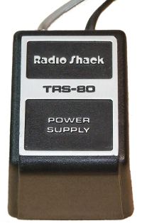
240V Version in Action")
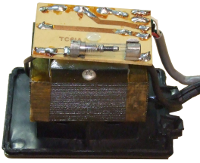
120V Version Working (Top)")
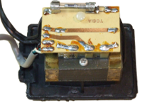
120V Version Working (Bottom)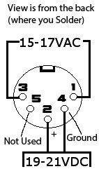
Pin Outs
Post Build Videos
Super technical explanation about the Power Supply … Page 52 from the TRS-80 Micro Computer Technical Reference Handbook
Click to Enlarge
The TRS-80 needs three voltage levels: +12 volts at about 350 milliamps; +5 volts at about 1.2 amps; and -5 volts at 1 milliamp. The +12 and -5 volts are needed by system RAM and everything needs +5 volts. The +12 volt and +5 volt supplies are regulated and current-protected against shorts. The -5 volts supply is not as critical as the other two supplies, and it uses a single zener diode for regulation. Stepped-down AC voltage is supplied to all regulator circuits from a U L approved “AC adapter”.
A/C Adapter
The AC Adapter is a large version of the type used for calculators and TV game products. Inside the plastic case is a single transformer with one primary and two secondary windings. The primary circuit is designed for 120 V AC and has an operating range of 105 to 135 V AC.
The secondary windings are both center-tapped. One secondary is rated at 14 volts AC at 1 amp. This winding is used for the +5 and -5 volt supplies. The other secondary winding has diodes connected and it outputs 19.8 VDC at about 350 milliamps. This circuit is used for the 12 volt supply. All voltage outputs and center taps are brought into the POWER input (J1).
+12V Power Supply
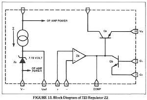
Unregulated DC voltage for the +12V supply is inputted at pin 2 of J1. When power switch S1 is closed, C8 filters the voltage and the net result is approximately 20 volts, which is applied to Q6 and regulator Z2. Figure 13 shows a simplified diagram of the internal circuitry in a 723 regulator chip. Figure 13 will help in the regulator operation discussion.
The filtered DC voltage from the Adapter and C8 is applied to pin 12 of Z2 and the emitter of series pass transistor Q6. The voltage applied to pin 12 allows a constant current source to supply zener current for Za. Pin 6 of Z2 will output a zener voltage of about 7.15 volts. Pin 6 is tied to pin 5, the positive input to operational amplifier Zb. The negative input to the op-amp is tied to the wiper of R10. Initially, pin 4 of Z2 is at ground, forcing the output of op-amp Zb to output about 7.15 volts. Transistor Oa turns on, which turns on pass transistor Q6. The pass transistor supplies voltage for current monitoring resistor R18 and to the resistor network R13, R10 and R12. If R10 is adjusted for 7.15 volts at its wiper, the op-amp will be balanced and Q6 will output only enough voltage to keep the loop stable. If output voltage dropped below 12 volts, Zb’s output would decrease which would force the current through Qa to decrease. Qa would cause Q6 to increase the current through it, and the output would rise back up to the 12 volt level. If the 12 volt line increased in voltage, the op-amp would cause Qa’s current to increase, forcing Q6 to drop down.
The transistor labeled Qb in Figure 13, is used to protect power transistor 06 against over-current damage. If R18 drops sufficient voltage to cause the resistor node at Z2, pin 2, to reach 12.6 volts, Qb will take command of Oa. As Qb is turned on, Qa turns off which starts turning Q6 off. The voltage at Z2, pin 10, must approach 14.7 volts before Qb takes charge of Oa. 14.7 volts at pin 10 means that the 12 volt supply is approaching its maximum design current of 480 milliamps. If a short develops across the 12V supply, Ob will activate, forcing Qa to shut down. With Qa off, Q6’s base rises to the input voltage level because of R16. Q6 snaps off the supply, preventing it from attempting thermal suicide. Once the short is removed, Qb will turn off and the system will operate normally.
Capacitor C13, connected between pins 13 and 4, is a frequency compensation capacitor. It prevents the op-amp loop from going into oscillation. C11 and C15 are the supply’s output filter and noise suppressors. Capacitors C28, C30, C32 and C34 are distributed along the 12 volt supply bus for transient suppression.
+5V Power Supply
The 5 volt power supply also uses a 723 regulator. Due to the current and voltage requirements, more components were stuck around the regulator for support. But the basic circuit operates the same. Figure 13 will also be used in this circuit.
For the 5 volt supply, the AC adapter supplies about 17 volts AC at J1, pins 1 and 3. Full-wave rectifier CR8, rectifies the AC. When 51 is closed, about 7 VDC is passed through the switch contacts and is filtered by C9.
The power supply for Z1 and the current source for zener Za is taken from the regulated side of R18 in the 12 volt section. Pin 7 is grounded as in Z2, but the zener output is handled differently. The 7.15 volt zener voltage is applied to the resistor network consisting of R6, R5 and R 11. When R5 has been adjusted for a 5 volt output on the supply bus, pin 5 of Z1 will be at about 5 volts. The negative input of the op-amp, Zb, is sourced through a 1.2K resistor, R7, and tied to the 5 volt bus. The op-amp controls Qa, which controls bias drive for Q3. Q3 is used to handle the greater base drive necessary for pass transistor Q4. Q4’s collector is tied to current sensing resistor, R4. R4 monitors the current the 5 volt bus is producing just as R18 did for the 12 volt bus.
Circuit operation is exactly the same for Z1 as it was for Z2. If op-amp Zb detects a rising or falling voltage condition at the output bus, it will adjust base current to Qa. Since Qa cannot handle the drive requirements for 04 directly, 03 is needed for current gain. During current limiting condition, 05 monitors the voltage across R4, which is a direct function of bus current. As Q5 begins to turn on. the node at R3 and R9 supplies more voltage for base drive of Qb. As Qb takes command of the regulator loop, Qa is commanded to start cutting Q3 off. Q3 begins to turn Q4 off and the circuit goes into current limiting. The current limiting action of Q5 starts to come into play when the voltage across R4 approaches 0.6 volt. Ohm’s Law tells us the bus current at this voltage level is approaching 1.82 amps.
C12, connected between pins 13 and 14 of Z1, performs the same compensation function as C13. C10 and C14 are the output filter and noise suppressors while the thirty-two 0.01 microfarad capacitors are distributed all over the Board to suppress transient spikes.
Notice zener diode CR1 on the 5 volt bus. This diode is used as crowbar circuit protection in case of catastrophic failure in the RAMs. If something happens in the system RAM circuit that causes a short between the 12 and 5 volt buses, CR1 would turn on, causing the 5 volt bus to go into current limiting. Since CR1 is a 6.2 volt zener, it would protect the TTL devices connected to the 5 volt bus from being damaged by a sudden 12 volt supply voltage. Normally, CR1 would be off with no current flowing through it.
NOTE: The 12 volt supply must be working properly before the 5 volt supply will operate correctly. Therefore, the 12 volt supply must be adjusted before the 5 volt supply.
-5V Power Supply
Source voltage for the -5 volt supply comes from the negative terminal of rectifier CR8. When switch 51 is closed, the negative DC is filtered by C1 and about -11 volts is applied to resistor R19. R19 is used to limit current for zener regulator CR2. a 5.1 volt device. The -5 volt circuit is about as simple a power supply as can be designed. C4 and C3 is the -5 volt supply filtering and noise suppressing caps, while C16 through C19 perform the transient suppression function.