Model III ROM Explained - Part 4 (Durda ROM)
Introduction
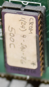
When Frank Durda IV passed away, his wife provided his collection to various archivists in the TRS-80 community. A Model 4 in that collection had a ROM which was under development by Frank and was never released to the public. That ROM had a "1(24) January 1986" label. This page is a disassembly of that ROM (and the other Model III ROM pages have been updated to account for Franks changes as alternative code), noting that the following are my findings:
- Since the Model III ROM tried to stay as close to the Model I ROM as possible, legacy bytes were still present in unused areas. Frank NOP'd them all.
- Moved as much code as possible from the end of the Model III ROM into the beginning of the Model III ROM. This was assisted by moving the PRINT SCREEN code out and by replacing a hidden name of "RON" in the code with the "CASS?" prompt. There were a bunch of changes in 0000H-0FFFH to accomplish this.
- Freed over 300 bytes in the 3000H-37FFH range by removing all the code which set out the keyboard map/translation tables and the printer translation table. He used bit manipulation instead of table lookups.
- Raised the base address for a SYSTEM cassette to be 42E8H instead of 4288H which stopped the SYSTEM tape from overwriting a LOT of Model III DOS RAM locations.
- Fixed 2 Bugs in the Model III ROM:
- Hitting BREAK at the filename inquiry of a SYSTEM command would reboot a Model III due to a bug in 02C3H-02C5H. This ROM returns to the READY prompt.
- Fixing a failure to tag an instruction as DATA because a byte was written to the wrong memory location (1BC1-1BC3, 1BDC-1BDE, and 1C67-1C69). This fix was the only change he made between ROM Address 1000H and 2FFFH
- Implemented code at 304BH to permit a boot from a Network 4 Controller which seem to be accessed by answering a number at the CASS? prompt other than 3 or 5.
- Implemented code at 316AH to permit a boot from a Hard Drive.
- Implemented code at 379CH which addressed hardware sitting at ports 30, 32, 33, 38, and 39
- Hid his initials in the ROM C
- Really streamlined some code to make all the above fit. Examples would be that if a routine needed to output a 0 to some ports and then a 1 to others, he would do those in that order with a BUMP or a XOR, or using the opcode LD (HL),00H instead of loading A with 0 first. He also broke out a few new memory addresses where he stored stuff.
3000 - Jump Table.
303C-303F - Frank Durda IV's Initials
3040-3047 - No Location Jumps Here. This may have been a Frank Durda Embedded Serial Number of 98 36 C3 7D 30 C3 6A 37.
3048 - This subroutine is called by the print routine when a LINE FEED or CARRIAGE RETURN is the current character.
304B - Part of the Network 4 Controller Boot - GOSUB'ed by 3076H and 30ECH
NOTE: 3810H is the row of the keyboard matrix holding 0 through 7.
Now we need to configure the Netork 4/Omninet
Next we load the Netork 4/Omninet boot code to 7000H in RAM
306F - This tests to see if the first byte of the RAM address to pass control to (4300H for Floppy or Hard Drive, 7300H for Network 4) is a FDH. If not, we have a problem and RETURN, with NZ set. Ohterwise, Bump the starting memory address beyond that first byte, and JUMP to it to pass control to that BOOT CODE.
- If A=FDH it sets the ZERO FLAG
- If A<FDH then the CARRY FLAG will be set
- if A>=FDH then the NO CARRY FLAG will be set.
304B - Part of the Network 4 Controller Boot - This was JUMPed to from 30EAH. This routine appears to process the CASS? answer, but beyond just H and L.
- If A=C1H it sets the ZERO FLAG
- If A<C1H then the CARRY FLAG will be set
- if A>=C1H then the NO CARRY FLAG will be set.
- If A=FCH it sets the ZERO FLAG
- If A<FCH then the CARRY FLAG will be set
- if A>=FCH then the NO CARRY FLAG will be set.
309C - This subroutine will display the message held in HL and then JUMP to the KBWAIT (Wait for Keypress) Routine.
30A2 - This is a VECTOR JUMP from 3015H - It resets all the ports, sets the interrupt to jump to 4046H, moved 76 bytes from 36AAH to 4000H, and reads disk sectors into 4000H+ until the interrupt fires.
NOTE: Port ECH stores miscellaneous controls.
- Bit 3: Alt. char. [0 = disable, 1 = enable]
- Bit 4: I/O bus [0 = disable, 1 = enable]
- Bit 5: Video waits [0 = disable, 1 = enable] ? Model 4 ONLY
- Bit 6: CPU clock speed [0 = 2 mhz, 1 = 4 mhz]
30C3 - This is in the middle of the machine setup routine - While this is a pass through to set up the machine / warm boot, it is also a jump point for a failure to boot from anything AND is a VECTOR jump from 3012H.
- Bit 0: Drive 0 Select
- Bit 1: Drive 1 Select
- Bit 2: Drive 2 Select
- Bit 3: Drive 3 Select
- Bit 4: Side Select (0 = Select Side 0, 1 = Select Side 1)
- Bit 5: Write Precompensation (0 = Disable WP, 1 = Enable WP)
- Bit 6: Wait State Generation (0 = Disable WSG, 1 = Enable WSG)
- Bit 7: Density Select (0 = Single/FM, 1 = Double/MFM)
NOTE: Port EAH is the RS-232 UART Control Register/Status Register. For output:
- Bit 0: Data Terminal Ready
- Bit 1: Request to End
- Bit 2: Break
- Bit 3: Parity Enable
- Bit 4: Stop Bits
- Bit 5: Select
- Bit 6: Word Length
- Bit 7: Parity (0=Odd, 1=Even)
- Bit 0: Busy
- Bit 1: Index/DRQ
- Bit 2: Track 0/Data Lost
- Bit 3: CRC error
- Bit 4: Seek error/Record not found
- Bit 5: If Reading, Record Type, if Writing, Write Fault/Head loaded
- Bit 6: Write Protect
- Bit 7: Not ready
- Bit 0: Busy
- Bit 1: Index/DRQ
- Bit 2: Track 0/Data Lost
- Bit 3: CRC error
- Bit 4: Seek error/Record not found
- Bit 5: If Reading, Record Type, if Writing, Write Fault/Head loaded
- Bit 6: Write Protect
- Bit 7: Not ready
- Bit 0: Drive 0 Select
- Bit 1: Drive 1 Select
- Bit 2: Drive 2 Select
- Bit 3: Drive 3 Select
- Bit 4: Side Select (0 = Select Side 0, 1 = Select Side 1)
- Bit 5: Write Precompensation (0 = Disable WP, 1 = Enable WP)
- Bit 6: Wait State Generation (0 = Disable WSG, 1 = Enable WSG)
- Bit 7: Density Select (0 = Single/FM, 1 = Double/MFM)
NOTE: 4049H is the RST 0 NMI Vector.
NOTE: Port F3H is the FDC Data Register (the data byte to be READ or WRITTEN to disk).
- Bit 0: Busy
- Bit 1: Index/DRQ
- Bit 2: Track 0/Data Lost
- Bit 3: CRC error
- Bit 4: Seek error/Record not found
- Bit 5: If Reading, Record Type, if Writing, Write Fault/Head loaded
- Bit 6: Write Protect
- Bit 7: Not ready
- Bit 0: Drive 0 Select
- Bit 1: Drive 1 Select
- Bit 2: Drive 2 Select
- Bit 3: Drive 3 Select
- Bit 4: Side Select (0 = Select Side 0, 1 = Select Side 1)
- Bit 5: Write Precompensation (0 = Disable WP, 1 = Enable WP)
- Bit 6: Wait State Generation (0 = Disable WSG, 1 = Enable WSG)
- Bit 7: Density Select (0 = Single/FM, 1 = Double/MFM)
NOTE: Port C1H is the hard drive controller board control register. Sending a 0 resets the hard drive controller board.
NOTE: Ultimately an interrupt will fire and pull us out of this seemingly endless loop.
313B - This routine will clear the stack, check the floppy drive status register after a read, and JUMP to 4300H to continue to DOS if successful, and jump to 310BH if errors were found.
- Bit 0: Busy
- Bit 1: Index/DRQ
- Bit 2: Track 0/Data Lost
- Bit 3: CRC error
- Bit 4: Seek error/Record not found
- Bit 5: If Reading, Record Type, if Writing, Write Fault/Head loaded
- Bit 6: Write Protect
- Bit 7: Not ready
314E - Hard Drive Routine - This routine is jumped from 3107H if the last disk read did not produce any of CRC ERROR, SEEK ERROR, and NOT READY.
NOTE: Port CBH is Register 3 for WD1010 Winchester Disk Controller Chip which is the Hard Disk Sector Number Register.
NOTE: Port CBH is Register 3 for WD1010 Winchester Disk Controller Chip which is the Hard Disk Sector Number Register.
If we are here, A = 0
- Bits 0-2: Head Number (0-7)
- Bits 3-4: Drive Number (00=#1, 01=#2, 10=#3, 11=#4)
- Bits 5-6: Sector Size (00=256, 01=512, 10=1024, 11=128)
- Bit 7: Extension (if this is set, Error Checking and Correction codes are in use and the R/W data [sector length + 7 bytes] do not check or generate CRC)
NOTE: Port CCH is Register 7 for WD1010 Winchester Disk Controller Chip and is the Hard Disk Error Status Register when used for INPut.
316AH - If we are here, the Hard Drive returned a READY code and we are going to boot from it.
NOTE: Port CEH is Register 6 for WD1010 Winchester Disk Controller Chip which is the register contaning Hard Disk Sector Size / Drive # / Head # as follows:
- Bits 0-2: Head Number (0-7)
- Bits 3-4: Drive Number (00=#1, 01=#2, 10=#3, 11=#4)
- Bits 5-6: Sector Size (00=256, 01=512, 10=1024, 11=128)
- Bit 7: Extension (if this is set, Error Checking and Correction codes are in use and the R/W data [sector length + 7 bytes] do not check or generate CRC)
319DH - This SUBROUTINE is called by 3543H and 355D.
31A5H - This SUBROUTINE is called by 3245H and 352CH. it writes 14 .46 volt pulses to tape, 14 .00 volt pulses to tape, waits for 78H loops, and RETURNS.
NOTE: Port FFH is the CASSETTE PORT. Bits 0-2 for OUTPUT control what is written. In the case of 01H a .46 volt spike is written.
NOTE: Port FFH is the CASSETTE PORT. Bits 0-2 for OUTPUT control what is written. In the case of 02H a .00 volt spike is written.
31BDH - This SUBROUTINE resets the cassette, sets the NMI, turns on interrupts, and RETURNs. It is ALSO a VECTOR jump from 400CH.
NOTE: 4213H holds the Default Interrupt Vector Setting
NOTE: Port FFH is the CASSETTE PORT.
NOTE: 4210H holds the bit mask for port ECH. Port ECH stores miscellaneous controls.
31D1 - Turn On The Cassette - Part 1. This will remove the return address, save DE and BC, restore the return address, and than blank the "**"
NOTE: Port ECH is the Miscellaneous Controls port, which covers clock on/off (Bit 0), cassette motor on or off (Bit 1), double size video on or off (Bit 2), and special character set select of Kana or misc (Bit 3). Higher bits are used for the Model 4 only.
31E8 - Turn On The Cassette - Actually Set the Bit Mask and Output the Command
NOTE: 4210H is the bit mask for Port ECH. Port ECH is the Miscellaneous Controls port, which covers clock on/off (Bit 0), cassette motor on or off (Bit 1), double size video on or off (Bit 2), and special character set select of Kana or misc (Bit 3). Higher bits are used for the Model 4 only.
NOTE: 4210H is the bit mask for Port ECH. Port ECH is the Miscellaneous Controls port, which covers clock on/off (Bit 0), cassette motor on or off (Bit 1), double size video on or off (Bit 2), and special character set select of Kana or misc (Bit 3). Higher bits are used for the Model 4 only.
31F3 - Reset the Cassette Port. This routine OUTputs a 0 to the Cassette Port FFH
NOTE: Port FFH is the cassette port. When outputting to FFH, Bits Zero and 1 set to: 00 is .85V, 01 is .46V, and 10 is 0.0V.
31F7 - Check to see if we have a PRINT # command and, if so, get the port number, validate that the next character is a , and return.
NOTE: 0253H is in the middle of the "Write a Byte to Cassette" Routine. It ends in a RETURN.
","
3203 - Vector for a SLOW cassette read. Frank saved 2 bytes by putting the memory addresses into BC and then using 1 byte instructions to maipulate the memory address.
NOTE: 321EH reads the tape until it finds a timing mark or the BREAK is hit.
NOTE: 4212H holds the cassette blinker counter.
NOTE: 4212H holds the cassette blinker counter.
321E - Cassette - Keep reading tape looking for a timing mark or BREAK.
NOTE: FFH is the Cassette Port.
322C - Cassette - Wait for the timing mark to pass and the next data to show up. Put that data into Bit 0 of D.
First, wait for 6EH Units (the length of the timing mark)
Reset the cassette port
Next, wait for 98H Units (the length until a data pulse is expected)
... continue
NOTE: Port FFH is the Cassette Port.
323FH - Vector for a SLOW cassette write. On entry A is the byte to output.
NOTE: D will be the DATA BYTE.
3256H - "Write a 0 Bit" by simply waiting the appropriate amount of time and doing nothing.
325C - SLOW tape header write
NOTE: 323FH is the Vector for a SLOW cassette write.
NOTE: 420CH is the TAPE WRITE VECTOR.
NOTE: A5H is the OUTPUT SYNC BYTE.
3272 - SLOW tape header read
NOTE: 3203H is the vector for a SLOW cassette read.
NOTE: 420EH is the TAPE READ VECTOR.
NOTE: 3220H reads the tape until it finds a timing mark or the BREAK is hit.
3299 - FAST tape header write.
NOTE: 32B8H is the VECTOR TO FAST WRITE.
NOTE: 420CH is the TAPE WRITE VECTOR.
NOTE: 32B4 restore all registers from the STACK, and Fill C with A, and JUMP to cassette write
NOTE: 7FH is the OUTPUT SYNC BYTE.
NOTE: 32B4 restore all registers from the STACK, and Fill C with A, and JUMP to cassette write
NOTE: A5H is the SLOW SYNC BYTE.
32B2 - Restore all registers from the STACK, and Fill C with A, and JUMP to cassette write.
32B8 - Save all registers to the STACK, and Fill C with A, GOSBUB to write out the START BIT ...
32BF - Call 3335H to Output a Bit 8 Times
32CAH - Read the start bit, read 8 bits, check for error, and flash the star
32D8H - FAST tape header read.
NOTE: 32C8H reads an verifies a byte.
Jump Table:
- xxxxxxx1 jumps to 3365H
- xxxxxx1x jumps to 3369H
- xxxxx1xx jumps to 4046H
- xxxx1xxx jumps to 403DH
- xxx1xxxx jumps to 4206H
- xx1xxxxx jumps to 4209H
- x1xxxxxx jumps to 44040H
- 1xxxxxxx jumps to 44043H
Routine continuation ... jumped from 330A
Jump Table:
- xxxxxxx1 jumps to 3365H
- xxxxxx1x jumps to 3369H
- xxxxx1xx jumps to 4046H
- xxxx1xxx jumps to 403DH
- xxx1xxxx jumps to 4206H
- xx1xxxxx jumps to 4209H
- x1xxxxxx jumps to 44040H
- 1xxxxxxx jumps to 44043H
NOTE: Port FFH is the cassette port. When outputting to FFH, Bits Zero and 1 set to: 00 is .85V, 01 is .46V, and 10 is 0.0V.
NOTE: Port FFH is the cassette port. When outputting to FFH, Bits Zero and 1 set to: 00 is .85V, 01 is .46V, and 10 is 0.0V.
334EH - READ a BIT
3363 - This is a Port E0H Masked Jump. If the MASKABLE INTERRUPT is xxxxxxx1, it jumps here.
NOTE: FFH is the Cassette Port.
337AH - Check for a Data Error.
- If A=22H it sets the ZERO FLAG
- If A<22H then the CARRY FLAG will be set
- If A>=22H then the NO CARRY FLAG will be set
338CH - Keyboard Routine - VECTORed from 3024H.
NOTE: 41FDH is the saved position in the keyboard scan.
NOTE: 4201H is the REPEAT DELAY COUNTER.
NOTE: 4201H is the REPEAT DELAY COUNTER.
OR L
NOTE: 41FEH is the saved IMAGE at the saved position in the keyboard scan data.
NOTE: 4201H is the REPEAT DELAY COUNTER.
NOTE: 4018H is the Right Shift Toggle in the keyboard device contol block.
- If A=L it sets the ZERO FLAG
- If A<L then the CARRY FLAG will be set
- if A>=L then the NO CARRY FLAG will be set.
33C5H - Inside Keyboard Routine - JUMPed to from the XOR commands above
33F2 - Inside Keyboard Routine
3404 - Inside Keyboard Routine
NOTE: 4019H holds the caps lock toggle in the keyboard DCB.
NOTE: 3840H holds ENTER (1), CLEAR (2), BREAK (4), Right Arrow (8), Line Feed (16), Left Arrow (32), and SPACE (64).
3440 - Inside Keyboard Routine
3446 - Inside Keyboard Routine
- If A=30H it sets the ZERO FLAG
- If A<30H then the CARRY FLAG will be set
- if A>=30H then the NO CARRY FLAG will be set.
- If A=3CH it sets the ZERO FLAG
- If A<3CH then the CARRY FLAG will be set
- if A>=3CH then the NO CARRY FLAG will be set.
3468 - Inside Keyboard Routine
346C - Inside Keyboard Routine
NOTE: 41FFH holds the Keyboard Scan Repeat Delay Count
NOTE: 4201H holds the Keyboard Scan Repeat Delay Counter
348D - Inside Keyboard Routine
- If A="8" it sets the ZERO FLAG
- If A<"8" then the CARRY FLAG will be set
- if A>="8" then the NO CARRY FLAG will be set.
NOTE: "8" is the first character on the 3820H keyboard row.
- If A="3" it sets the ZERO FLAG
- If A<"3" then the CARRY FLAG will be set
- if A>="3" then the NO CARRY FLAG will be set.
- If A="7" it sets the ZERO FLAG
- If A<"7" then the CARRY FLAG will be set
- if A>="7" then the NO CARRY FLAG will be set.
- If A="3" it sets the ZERO FLAG
- If A<"3" then the CARRY FLAG will be set
- if A>="3" then the NO CARRY FLAG will be set.
34AA - Inside Keyboard Routine
- If A="4" it sets the ZERO FLAG
- If A<"4" then the CARRY FLAG will be set
- if A>="4" then the NO CARRY FLAG will be set.
34B6 - Inside Keyboard Routine
- If A="6" it sets the ZERO FLAG
- If A<"6" then the CARRY FLAG will be set
- if A>="6" then the NO CARRY FLAG will be set.
34C1 - Inside Keyboard Routine
- If A="lt;" it sets the ZERO FLAG
- If A<"lt;" then the CARRY FLAG will be set
- if A>="lt;" then the NO CARRY FLAG will be set.
34CFH - Inside Keyboard Routine - I'm not convinced that the code here did anything.
34E5 - Network 4 BOOT Routine - Jumped here if the keypress was not a 3.
NOTE: Port E9H is the RS-232 Baud Rate Selects and Sense Switches. Outputting to Port E9H will set the Baud Rate as follows:
- Bits 0-3 - Select the Receive Rate
- Bits 4-7 - Select the Transmit Rate
NOTE: Port E8H is the RS-232 Status Register & Master Reset. Input:
- Bit 4: Ring Indicator
- Bit 5: Carrier Detect
- Bit 6: Data Set Ready
- Bit 7: Clear to Send
NOTE: Port EAH is the RS-232 UART Control Register/Status Register. For output:
- Bit 0: Data Terminal Ready
- Bit 1: Request to End
- Bit 2: Break
- Bit 3: Parity Enable
- Bit 4: Stop Bits
- Bit 5: Select
- Bit 6: Word Length
- Bit 7: Parity (0=Odd, 1=Even)
NOTE: Port E8H is the RS-232 Status Register & Master Reset. Input:
- Bit 4: Ring Indicator
- Bit 5: Carrier Detect
- Bit 6: Data Set Ready
- Bit 7: Clear to Send
NOTE: 4300H is the traditional memory location for a DOS boot.
NOTE: Port EAH is the RS-232 UART Control Register/Status Register. For output:
- Bit 0: Data Terminal Ready
- Bit 1: Request to End
- Bit 2: Break
- Bit 3: Parity Enable
- Bit 4: Stop Bits
- Bit 5: Select
- Bit 6: Word Length
- Bit 7: Parity (0=Odd, 1=Even)
3518 - This SUBROUTINE is called during WARM BOOT. It handles setting up the Port 84H Settings (as explained in this section).
NOTE: Port 84H handles miscellaneous memory items. Output:
- Bits 0-1: Identify the Model of the Computer
- Bit 2: Video Display Mode [0=64x16, 1=80x24]
- Bit 3: Reverse Video
- Bit 4-6: RAM Bank Select
- Bit 7: Video Page Select [0=Page 0, 1=Page 1]
3523H - This SUBROUTINE tests the active CPU SPEED and sets Z accordingly (Z=2mhz, NZ=4mhz)
NOTE: 4210H holds the bit mask for port ECH. Port ECH stores miscellaneous controls.
3529 - Deal with the cursor.
NOTE: Port ECH is the Miscellaneous Controls port, which covers clock on/off (Bit 0), cassette motor on or off (Bit 1), double size video on or off (Bit 2), and special character set select of Kana or misc (Bit 3). Higher bits are used for the Model 4 only.
NOTE: 4022H holds the Cursor ON/OFF Flag and will be 0 if the cursor is off, or the underscore character otherwise.
NOTE: 401CH holds the Cursor Blink Switch and will be 0 for Blink, and anything else for No Blink.
NOTE: 401AH is the memory location that stores the cursor blink count.
NOTE: 401AH is the memory location that stores the cursor blink count.
NOTE: 401AH is the memory location that stores the cursor blink count.
NOTE: 401BH holds the cursor blink status - 0 = Off, Anything Else = On.
NOTE: 4020H holds the current cursor position.
NOTE: 4023H holds the cursor character.
3555H - Update the heartbeat and deal with the time, including rollover to the next day, month, and year.
NOTE: 4216H is the heartbeat counter.
NOTE: 4216H is the heartbeat counter.
NOTE: 0266H points to the TIME DATA of the number of seconds in a minute, the number of mnutes in an hour, and the number of hours in a day.
NOTE: If HL is 4217H then it is seconds, 4218H then it is minutes, 4217H then it is hours.
NOTE: 0266H points to the TIME DATA of the number of seconds in a minute, 0267H points to the number of mnutes in an hour, and 0268H points to the number of hours in a day.
NOTE: If HL is 4217H then it is seconds, 4218H then it is minutes, 4219H then it is hours, and 421AH then it is YEARS.
NOTE: 0266H points to the TIME DATA of the number of seconds in a minute, 0267H points to the number of mnutes in an hour, and 0268H points to the number of hours in a day.
NOTE: 421BH holds the current DAY portion of the date.
NOTE: 421BH holds the current MONTH portion of the date.
NOTE: 421BH holds the DAY portion of the date.
NOTE: DE currently points to the memory locations housing the of days in each month.
NOTE: If this is not a loop, the HL holds the day portion of the date.
NOTE: A CP actually subtracts 1E from A without modifying A, but the flags are set accordingly. Here, if A is < 1E then the CARRY FLAG will be set.
NOTE: 421AH points to the current YEAR.
NOTE: 421BH points to the current DAY.
NOTE: 421BH points to the current MONTH.
NOTE: This will test against a month 13. If A is < 13, then the CARRY FLAG will be set.
NOTE: 421BH points to the current DAY.
NOTE: 421BH points to the current YEAR.
3593 - Check to see if the clock is on and exit back out if it is off OR the heartbeat shows that the clock was just updated. Pass through otherwise.
NOTE: 4210H holds the bit mask for port ECH. Port ECH stores miscellaneous controls.
NOTE: 4216H is the heartbeat counter.
NOTE: A CP actually subtracts 1E from A without modifying A, but the flags are set accordingly.
35A1 - Put the Clock 10 characters from the end of the first line. We enter this routine with HL pointing to the screen location 10 characters from the end of the first line.
NOTE: 4219H is the current HOUR.
NOTE: This routine is also used to convert the date, and C will be swapped out to a / for that routine.
NOTE: This is because we need to convert 3 numbers, so we will loop 3 times.
NOTE: This will be HOUR (4219H) on the first pass, MINUTE (4218H) on the second pass, and SECOND (4219H) on the third pass.
NOTE: 2F is a / which is also 1 character below a 0.
35BCH - Put the DATE 8 characters from the end of the first line. We enter this routine with HL pointing to the screen location and we just jump into the prior routine with a different pointer to the DATE and a change in the delimeter to a /.
NOTE: 421CH holds the current MONTH.
35C3 - Maskable Interrupt Handler.
NOTE: 4046H is Interrupt Vector 2 and contains a JUMP to 35A9H. It is commonly used by the clock.
NOTE: 403DH is Interrupt Vector 3 and contains a JUMP to 35FAH.
NOTE: 403DH is Interrupt Vector 4 and contains a JUMP to 35FAH.
NOTE: 4209H is Interrupt Vector 5 and contains a JUMP to 35FAH.
NOTE: 4209H is Interrupt Vector 6 and contains a JUMP to 35FAH.
NOTE: 4043H is Interrupt Vector 7 and contains a JUMP to 35FAH.
3601 - RS-232 Initialization Routine. I'm [guessing] that IX is set to 41F5H
NOTE: Port EAH is the RS-232 UART Control Register/Status Register. Input:
- Bit 3: Parity error (1=True)
- Bit 4: Framing Error (1=True)
- Bit 5: Overrun (1=True)
- Bit 6: Data Sent (1=True)
- Bit 7: Data Ready (1=True)
NOTE: 41F8H holds the baud rate code.
NOTE: Port E9H is the RS-232 Baud Rate Selects and Sense Switches. Outputting to Port E9H will set the Baud Rate as follows:
- Bits 0-3 - Select the Receive Rate
- Bits 4-7 - Select the Transmit Rate
NOTE: 41F9 holds the RS-232 Configuration Code.
NOTE: Port EAH is the RS-232 UART Control Register/Status Register. For output:
- Bit 0: Data Terminal Ready
- Bit 1: Request to End
- Bit 2: Break
- Bit 3: Parity Enable
- Bit 4: Stop Bits
- Bit 5: Select
- Bit 6: Word Length
- Bit 7: Parity (0=Odd, 1=Even)
NOTE: 41FAH holds the RS-232 Wait Switch.
NOTE: 41E9H is the RS-232 Input DCB: Bit 2 is DRIVER ON or OFF.
NOTE: 41F1H is the RS-232 Output DCB: Bit 2 is DRIVER ON or OFF.
NOTE: Port E8H is the RS-232 Status Register & Master Reset. Input:
- Bit 4: Ring Indicator
- Bit 5: Carrier Detect
- Bit 6: Data Set Ready
- Bit 7: Clear to Send
362D - This will zero out a bunch of RS-232 Related Ports and Memory Addresses. We wind up here if there is no RS-232 or the RS-232 CONFIGURATION CODE is 0.
NOTE: 41F0H is the 1 characer output buffer for the RS-232 Output DCB.
364AH - RS-232 Input Routine.
NOTE: 41E8 is the Input Buffer of the RS-232 Input DCB.
NOTE: 41E9H is the RS-232 Input DCB:
- Bit 2: Driver On/Off
- Bit 1: Wait/No Wait
NOTE: Bit 2 of 41E9 contains the DRIVER ON/OFF.
NOTE: Bit 1 of 41E9 contains the WAIT/NO WAIT.
3665 - A JUMP here puts the character held in Register A (which was read from the RS-232C) and puts it in the memory location pointed to by HL; and then RETURN.
3667 - RS-232 Input Routine - This checks for DATA READY and if so, takes in a character from the RS-232. Exits with NC set if DATA NOT READY.
NOTE: Port EAH is the RS-232 UART Control Register/Status Register. Input:
- Bit 3: Parity error (1=True)
- Bit 4: Framing Error (1=True)
- Bit 5: Overrun (1=True)
- Bit 6: Data Sent (1=True)
- Bit 7: Data Ready (1=True)
NOTE: Port EBH is the RS-232C Data Register. It contains the data received from the RS-232C.
3670 - RS-232 Input Routine - This SUBOUTINE Reads a Byte from the RS-232 until a 00H is read.
3676 - RS-232 Output Routine.
NOTE: 41F1H is part of the RS-232 Output DCB:
- Bit 2: Driver ON/OFF
- Bit 1: Wait/No Wait
NOTE: Port EAH is the RS-232 UART Control Register/Status Register. Input:
- Bit 3: Parity error (1=True)
- Bit 4: Framing Error (1=True)
- Bit 5: Overrun (1=True)
- Bit 6: Data Sent (1=True)
- Bit 7: Data Ready (1=True)
NOTE: 41F1H Hholds DRIVER ON/OFF in BIT 2, and WAIT/NO WAIT in BIT 1.
NOTE: 4203H JUMPS to 022EH and is the break vector for tape and RS-232.
368D - Inside RS-232 Output Routine - If the RS-232 Returned READY TO SEND, then we are here to do the send..
NOTE: HL is likely pointing to 41EEH, which is the Driver Address for the RS-232 Output DCB.
3698-36A9 - Message Storage Area for ROM Version
36AAH - Initial Vectors and DCBs for RAM 4000H-404BH.
36F5H - UNUSED.
36F9H - Initial Vectors and DCBs for RAM 41E5H-4224H.
3739 - This is jumped to from the middle of the tokenize routine. It checks for items inside quotes.
NOTE: 409FH is the DATA FLAG.
NOTE: XOR is an exclusive OR, meaning that if the 2 things are the SAME the result is 0, and if the 2 things are DIFFERENT, the result is 1.
NOTE: 409FH is the DATA FLAG.
NOTE: 06AAH is in the middle of the KEYBOARD DRIVER ENTRY ROUTINE.
NOTE: 409FH is the DATA FLAG.
NOTE: 06A8H is in the middle of the KEYBOARD DRIVER ENTRY ROUTINE.
NOTE: 06A8H is the REM processor in the middle of the KEYBOARD DRIVER ENTRY ROUTINE.
3757 - I/O Re-Router.
376A - This subroutine is called by the print routine when a 01H or LINE FEED or CARRIAGE RETURN is the current character.
- If A=E0H it sets the ZERO FLAG
- If A<E0H then the CARRY FLAG will be set
- if A>=E0H then the NO CARRY FLAG will be set.
- If A=C0H it sets the ZERO FLAG
- If A<C0H then the CARRY FLAG will be set
- if A>=C0H then the NO CARRY FLAG will be set.
NOTE: 4220H-4221H is the destination device nName for ROUTE Routine. 2 Bytes
3781H Print Screen Routine. Used to be 01D9H-01F7H
379C - This is part of the warm reset routine from 3015H and fires right after interrupt mode is set to 1, non maskable interrupts are turned off, and the stack pointer is reset to 407DH.
- 00H - restore
- 80H - read sector
- A0H - write normal sector
- A1H - write read protect sector
- C0H - read address
- D0H - reset; puts FDC in mode 1
- E0H - read track
- F0H - write track
37C2H - This SUBROUTINE is called inside the HARD DRIVE routine once the READY status is set. On entry A is either 10H (Binary: 0001 0000; Bit 4 on) or 20H (Binary: 0010 0000; Bit 5 on).
NOTE: Port CCH is Register 7 for WD1010 Winchester Disk Controller Chip and is the Hard Disk Error Command Register when used for OUTput. 70H is "Seek with a 35 milisecond stepping rate". 16H is "Restore with a 3 milisecond stepping rate"
NOTE: Port CFH is Register 7 for WD1010 Winchester Disk Controller Chip and is the Hard Disk Error Status Register when used for INPut.
NOTE: Bit 0 is LOW on Port CFH if there is no error.
37CD - This is inside the HARD DRIVE routine once the READY status is set. If we are here, we got an error on the read despite the drive being READY.
NOTE: Port C1H is the hard drive controller board control register. Sending Bit 3 high means ENABLE CONTROLLER and Bit 4 high means RESET CONTROLLER.
NOTE: Port C1H is the hard drive controller board control register. Sending Bit 3 high means ENABLE CONTROLLER .
37D7H - I don't see that this is ever called or executed.
37E8H - Hidden 2 Byte Code - Printer Input/Output.
37EAH - BASIC TIMES (DATE$+" "+TIME$)
NOTE: This is to set up for a 17 Byte String.
NOTE: 40D4 is the string pointer.